Abstract
Experiments were performed to obtain the coefficient of friction (COF) between pickleball paddles and balls and to determine its influence on rebound spin of the ball. Balls were fired at both legal and illegal paddles, a court surface, and a sandpaper surface. Incident impact angles were varied between 10 and 90 degrees and were measured from the paddle surface. Results indicate that there is a range of angles over which the ball grips the paddle and a range over which the ball slides throughout impact. If the ball grips, maximum theoretical friction-caused spin will be achieved. This maximum spin is the same for all paddles hitting balls incident at the same angle, spin, and velocity. Each paddle has a slide-grip transition angle, below which the ball slides throughout impact, and above which it grips and achieves maximum spin. The transition angle varies with the static coefficient of friction. Where paddles' gripping ranges overlap (generally greater than 45 degrees from the paddle surface), all paddles produce the same spin, regardless of COF. In the sliding range (less than 45 degrees from paddle surface), paddles with higher COF produce more spin, but spin is greatly reduced compared to the griping range. During play, most shots are incident at angles above the transition angle. If so, there will be little or no difference in rebound spin for most shots for all paddles, regardless of surface roughness and COF.
Note: An abridged, nontechnical summary of this experiment is presented here.
1. Introduction
Spin generation is a hot topic these days because several pickleball paddles have been designated illegal for play due to their rough surfaces and assumed influence on spin. But is this really true? Does spin depend on surface roughness? If so, how and in what circumstances? Based on TWU tennis experiments [1, 2], we knew the probable answer, but you really never know until you do the specific experiment ... so we did. We fired pickle balls at various paddles and surfaces and measured all the incident and rebound parameters to see how they all interacted to produce rebound spin. Rod Cross did a similar experiment measuring the spin of steel balls impacting a smooth granite surface [3] with very similar conclusions, in spite of the radically different interacting surfaces.
1.1 Incident Parameters
A pickle ball with mass m (26 g) and radius R (37 mm) is incident on a clamped paddle at angle θ with velocity v (Figure 1). Velocity can be separated into two perpendicular components — velocity parallel to the surface (vx) and velocity perpendicular to the surface (vy).
The equations of motion during impact are given by
(1) F = -m(vx1 - vx2) / t
and
(2) N = m(vy1 - vy2) / t
and
(3) RF = Icm(ω2 - ω1) / t
where Icm = αmR2 is the moment of inertia about the center of mass, α is 0.66 for a hollow sphere, F is the friction force parallel to the surface, N the rebound force perpendicular to the surface, ω is the angular velocity, RF is the torque on the ball due to friction, and t is time of impact. Incident variables have a subscript 1 and rebound variables subscript 2.
Incident spin (angular velocity or ω) may be clockwise (CW), here given as positive, or counter-clockwise (CCW), given as negative. If ω is positive, a point at the top of the ball is moving to the right (positive), and a point at the bottom is moving to the left (negative), and vice versa for a CCW spin. Angular velocity is measured in radians per second, but it can be converted to linear velocity by multiplying ω by the radius — Rω. At the contact point, Rω may be in the same or opposite direction as vx. The net incident contact velocity (vc1) is given as
(4) vc1 = vx1 - Rω1.
In short, the ball as a whole moves in a given direction at given speed while the contact point may be moving in the same or opposite direction due to spin. The sum of these motions is the net speed and direction of the contact point of the collision. This in turn determines the direction of the friction reaction force.
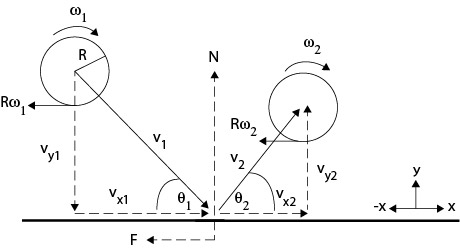
Figure 1 — Bounce geomentry. The diagram is a generalized scenario. The actual directions and magnitudes of the bounce variables will depend on the incident parameters. For example, ω2 could be spinning either clockwise or counter-clockwise.
1.2 Reaction Forces
During the collision, the ball and paddle exert equal and opposite forces on each other. The force exerted by the ball on the paddle is the applied force and the force exerted by the paddle on the ball is the reaction force. Each force has perpendicular components parallel and perpendicular to the surface. The parallel reaction force is friction and the perpendicular is the normal force (N). Friction alters spin and rebound angle. The normal force determines rebound speed, but it can also influence spin if it acts a distance (D) behind or ahead of the center of mass (CM) as shown in Figure 2.
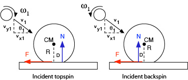
Figure 2 — Normal force offset. Incident impact shifts the normal force forward due to braking motion. Incident topspin rotating into the paddle in front of the CM will accentuate that shift forward and incident backspin rotating into the paddle behind the CM will shift it less forward or even backward if the spin is substantial.
Normal force offset occurs on oblique impacts due to the braking motion of impact which moves the impact and normal forces forward. It also occurs when topspin rotates into the paddle in front of the CM or backspin rotates into the paddle behind the CM. This displacement of the normal force is referred to as the "normal force offset". This offset force can act add to or subtract from the spin caused by the friction force. Combining Eq. 1-3, the net spin due to friction and normal forces is
(5) RF - DN = Icm(ω2 - ω1)
The friction force (F) works opposite the direction of motion or potential motion at the contact point. In addition to friction as defined in Eq. 1, it is also given as
(6) F = μN
or, rearranged,
(7) μ = F / N
where μ is the coefficient of friction (COF) and N is the perpendicular force pressing the surfaces together. If friction is resisting the initiation of sliding, it is defined as static friction and is given as Fs = μsN, where subscript "s" indicates "static." If friction is acting to reduce existing sliding, it is sliding friction and is given by Fk = μkN, where subscript "k" means "kinetic". Sliding friction is usually less than static friction because it requires less force to keep an object sliding than to initiate sliding. Equation 7 makes this clear indicating that the force to initiate or continue sliding is a fraction of the force pushing the objects together.
Friction causes changes in vx, Rω, and vc. Friction exerts a torque at the contact point which either increases or decreases spin and vx. Figure 3 shows how the direction of the friction force depends on incident parameters. This is complicated a bit by the direction of the paddle swing. The experimental impacts were with a clamped, stationary paddle. But the analysis does not differ with a moving paddle. It is still the net contact velocities that matter. In general, in Fig. 3 and others, a rising ball is equivalent to a falling paddle and a falling ball is equivalent to a rising paddle. It is the net of paddle and ball contact velocities that matters. Therefore we have no need for a moving paddle for the analysis.
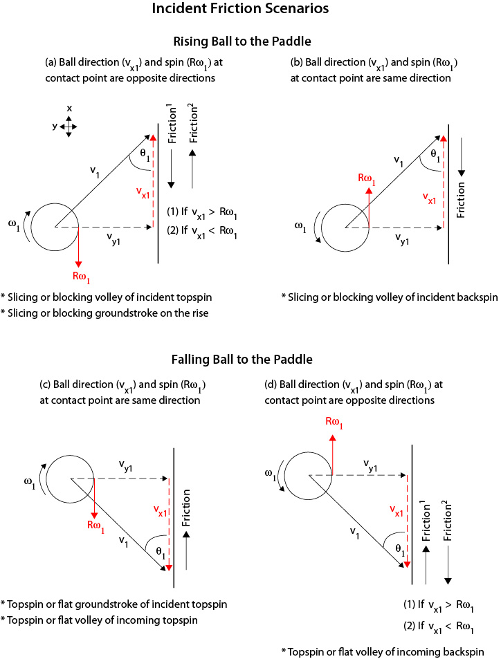
Figure 3 — Incident variables. Friction acts opposite the net linear and rotational velocity of the contact point. As a result, incident spin can be reduced, increased, or reversed in direction. Topspin rising toward the paddle (3a) is the same as backspin falling (3d) and backspin rising (3b) is the same as topspin falling (3c).
Figure 3c is the most common scenario. This is typical either when intercepting a topspin shot with a volley or hitting a shot after it bounced and reached its bounce apex. Figure 3a would apply to hitting a ball after the bounce but still on the rise. Almost all balls approach the paddle with topspin after bouncing on the court. A ball volleyed out of the air before it bounces can approach the paddle with backspin however. This is the situation in Fig. 3b and 3d.
Friction works opposite the direction of motion of the contact point (vc1). If vx1 and Rω1 are in the same direction (b and c in Fig. 3), friction will act in the opposite direction. If they are in opposite directions (a and d in Fig. 3), the friction direction will depend on whether vx1 is greater than or less than Rω1, and this in turn will depend on the angle of incidence, θ. As a result, incident ω and vx can be reduced, increased, or reversed depending on the net direction of the contact point.
1.3 Maximum Spin Limit
But there is a theoretical limit to how much friction can change spin. For example, in Figure 3a, if vx1 > Rω1, friction will act opposite vx1. This will decrease vx1 and increase Rω1, but this only occurs up to the limit where the linear speed forward will be equal and opposite the rotational speed backward at the contact point. The two speeds cancel and there is no relative motion (sliding) of the ball on the paddle and therefore the friction force decreases to near zero. The ball is said to grip the surface. When this occurs, no matter the surface roughness, no further significant spin will be added due to the friction force. gripping occurs only if friction is strong enough and acts long enough to induce it. This gripping, no friction condition is represented by
(8a) vc2 = vc1 - Δvx - ΔRω = 0
or,
(8b) vx2 = -Rω2
where vc2 is the net contact speed at liftoff, Δvx and ΔRω are the change (Δ) in the linear and rotational contact velocities during impact, and vx2 and Rω are liftoff linear and rotational velocities at the contact point.
If the linear and rotational velocities are in the same direction (Fig. 3b and 3c), the rotation will have to be totally reversed and then increased until the two velocities are equal and opposite. If vx1 and Rω1 are incident in opposite directions (Fig.3a and 3d), then it is easier to achieve the gripping, no friction condition of vx2 = -Rω2. If gripping occurs, then the resulting rebound spin will be the same for all paddles, given a fixed incident angle and velocity.
It is possible to determine whether gripping occurs by comparing rebound spin to the theoretical maximum spin achievable by friction alone. By combining equations 1-4 and 8a, it can be shown that if gripping occurs, then
(9) vx2t = vx1 - vc1 / 2.499
and
(10) ω2t = ω1 + vc1 / .063
where vx2t and ω2t are the theoretical maximum linear and angular velocities due to the influence of friction.
2. The Experiment
2.1 Static Friction
To determine the spin potential of a paddle, you first have to measure its COF. The static COF is much easier to measure than the sliding COF (see section 4.2). Figure 4 shows the setup to measure μs.
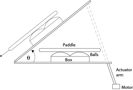
Figure 4 — Test Rig For Static COF. Four balls (Selkirk Outdoor Competition) are packed into a container and a paddle is placed on top of the balls. An actuator arm raises the lever arm until the paddle begins to slide. The angle θ is then used to calculate μs the static COF, as shown in Figure 5.
The calculations to determine μs are shown in Figure 5.
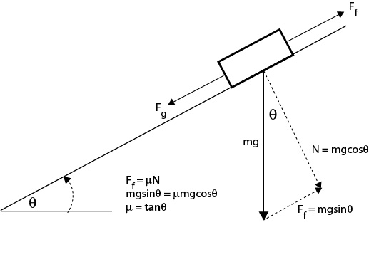
Figure 5 — Calculations to determine μs where m is mass, g is acceleration due to gravity, and θ is the incline angle.
A total of six surfaces were tested: 3 USPA friction-approved paddles (Head, Yonex, Vulcan), 1 USPA friction-banned paddle (CRBN), a sandpaper surface, and a USA Open tennis court surface. The static COFs obtained varied from 0.142 to 0.690 for the normal paddles, 0.582 for the court surface and 0.9+ for the sandpaper surface (the sandpaper COF is estimated since the test rig maximum capable measurement was about 0.9). (A list of COFs for over 100 paddles can be seen here.)
| Table 1 Friction Surfaces | ||||
|---|---|---|---|---|
| Paddle/surface | Static COF | |||
| Vulcan 710 Max | 0.142 | |||
| Yonex Vcore MW | 0.309 | |||
| CRBN 1 16 mm unserialized (unapproved) | 0.552 | |||
| US Open court surface | 0.589 | |||
| Head Radical Tour CO | 0.69 | |||
| Sandpaper (60 grit) | 0.9+ | |||
Table 1 — Paddles and surfaces tested to see the correlation between static COF and rebound spin. (Note: the sandpaper covered paddle never slid because the device's maximum angle was not sufficient for the paddle to slide. Hence the 0.9+ designation.)
2.2 Static COF Correlation With Spin
To test the correlation of COF to spin, paddles were secured to an adjustable incline bench capable of altering the ball's angle of impact from about 10 to 90 degrees, as measured from the paddle surface. Balls were fired at the paddles using a device that launched balls with velocity between 3 and 7 m/s (7-16 mph). Incident spins were varied between -500 to 800 rpm, with clockwise spin as positive (incident topspin) and counter-clockwise as negative (incident backspin). Only 3 paddles were tested with incident topspin (Head, Yonex, Vulcan) and 6 tested with incident backspin (Head, Yonex, Vulcan, CRBN, court surface, sandpaper). A minimum of two shots were fired at each angle. Impacts were filmed at 300 fps and exported into Tracker motion analysis software.
3. Results
Figures 6 and 7 show the results comparing actual spin to the theoretically possible friction-only spin calculated from Eq. 10. Figure 6 displays the case of incident linear and rotational contact velocities in opposite directions (as in Fig. 3a). This is the usual case for a ball after it has bounced on the court and has reached its apex, and also when you slice volley a ball that is approaching with topspin. It is also the case for hitting a topspin volley on a ball with incoming backspin (Fig. 3d). In all these cases, the ball grips the paddle at all incident angles and all three paddles produce the same spin regardless of COF.
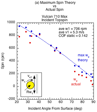
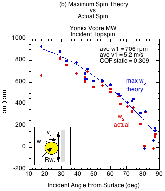
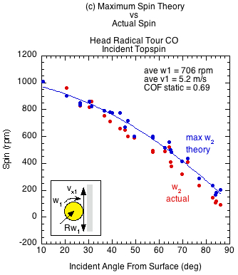
Figure 6 — Incident linear and rotational velocities in opposite directions. The ball grips at all incident angles regardless of static COF. At the contact point, the rebound spin velocity Rω2 is equal and opposite the linear ball velocity vx2. The contact velocity is thus zero and all paddles produce about the same spin at all angles of incidence. The divergence of actual spin from the theoretical maximum is due to the normal-offset torque. The braking motion of impact moves the normal force forward as does the clockwise topspin into the paddle in front of the CM. The normal force then works in the opposite direction of the friction force, reducing the spin from its maximum potential.
Figure 7 shows the results for impacts matching Fig. 3b and 3c — incident linear and rotational contact velocities in the same direction. This scenario occurs when volleying an approaching ball that has backspin (Fig. 3b) or hitting a topspin groundstroke of a ball after a bounce but still on the rise (Fig. 3c).
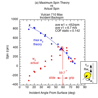
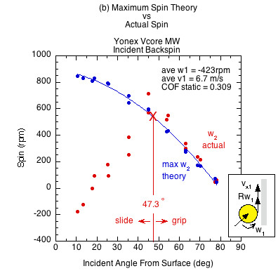
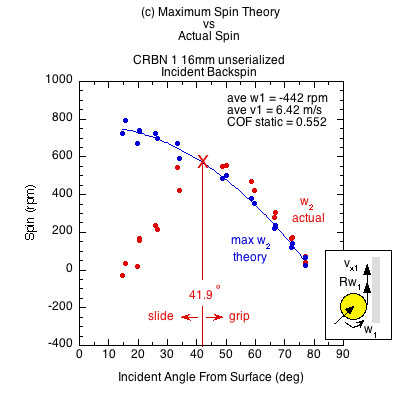
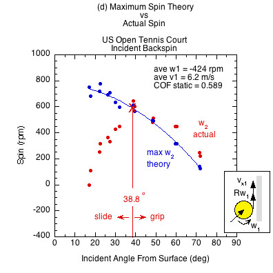
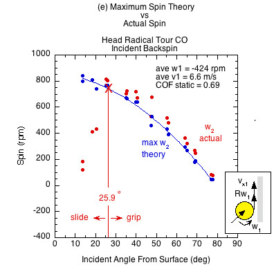
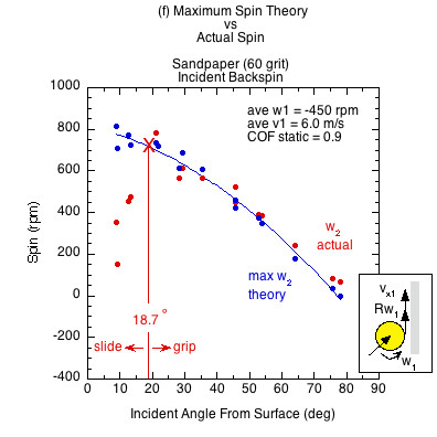
Figure 7 — Incident linear and rotational contact velocities in the same direction (as in Fig. 3b an 3c). All surfaces demonstrate both a sliding and gripping range, depending on the static COF and angle of incidence. Higher COF surfaces grip over a larger range of incident impact angles and slide over a smaller range. In the gripping range, friction achieves maximum possible spin but then that is increased by the normal offset force, which acts behind the CM due to the backspin into the paddle. This torque is in the same direction as the friction torque, increasing spin from that possible by friction only. In the sliding range there is not enough friction to achieve maximum spin. The normal offset force acts to make up some of that, but in comparison to the lack of friction, it is inconsequential. Therefore, in the sliding range the actual spin is dramatically reduced from the theoretical maximum friction caused spin.
The theoretical maximum spin curve is the curve of possibility — of what is and is not attainable by friction alone. In the gripping range, divergence from that curve is due to torque caused by the normal offset force. In the sliding range, divergence is caused primarily from lack of friction.
There is also a prediction curve (Fig. 8). It predicts/describes actual spin in both the gripping and sliding range. Solving Eq. 5 for ω2, we get
(10) ω2 = ω1 + (R(vx2 - vx1) - D(vy2 - vy1)) / αR2
where, from Eq. 5, D is given by
(11) D = αR2( ω2 - ω1) / (vy2 - vy1)
Figure 8 shows the actual, possible, and predicted data points for ω2 for all surfaces. The actual and predicted coordinates are virtually identical.
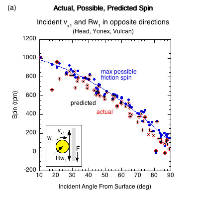
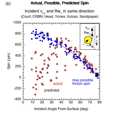
Figure 8 — Actual, possible, and predicted spin data points for (a) opposite direction incident linear and rotational contact velocities and (b) same direction incident linear and rotational contact velocities. Graphs are of all surfaces tested for each input condition.
4. Discussion and Analysis
Figure 6 shows that if Rω1 and vx1 are in opposite directions at the contact point, the ball grips the surface at all angles regardless of COF and surface roughness. All incident angles are in the gripping range and all spins from all paddles are the same.
It is different in Fig. 7 for incident impacts where Rω1 and vx1 are in the same direction at the contact point. The results of Figure 7 are summarized in Table 2.
| Table 2 Sliding and Gripping Ranges if Contact Velocites (Rω1 and vx1) Are Same Direction | ||||
|---|---|---|---|---|
| Paddle/surface | Static COF | Slide Range (deg.) | Grip Range (deg.) | |
| Vulcan 710 Max | 0.142 | 59.7 | 30.3 | |
| Yonex Vcore MW | 0.309 | 47.3 | 42.7 | |
| CRBN 1 16 mm unserialized (unapproved) | 0.552 | 41.9 | 48.1 | |
| US Open court surface | 0.589 | 38.8 | 41.2 | |
| Head Radical Tour CO | 0.69 | 25.9 | 64.1 | |
| Sandpaper (60 grit) | 0.9+ | 18.7 | 71.3 | |
Table 2 — Sliding and gripping ranges. Higher static COF correlates with wider gripping ranges and smaller sliding ranges. Where gripping ranges overlap, all surfaces produce the same spin. In the sliding range, surfaces with higher static friction generate more spin. Most shots are hit in the overlapping gripping range.
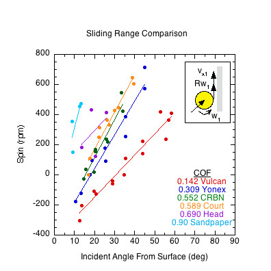
Figure 9 — Sliding Range. Range of angles over which the ball slides on each paddle. Except for the lowest COF paddle, the ball slides on paddles/surfaces when incident at less than 45 degrees from the surface. At each sliding range angle, the spin will be highest in order of static COF.
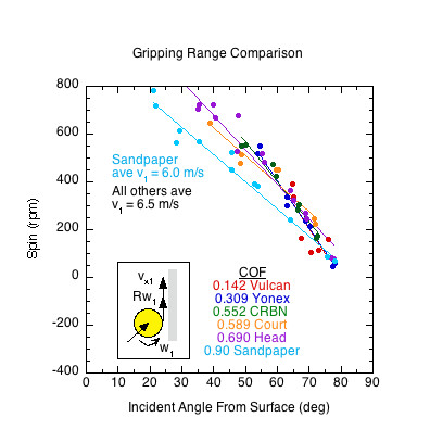
Figure 10 — Gripping Range. Range of angles over which the ball grips on each paddle. Gripping occurs on all paddles above 60 degrees from the surface and most will grip above 45 degrees. At angles above the sliding range, all paddles will produce about the same spin. The incident velocity was slower for the sandpaper impacts so it produced less spin than the others but produced the maximum gripping spin for that velocity. If the sandpaper were incident at the same speed, it would plot with the rest.
4.1 Observations
- When rotational and linear contact velocities are in opposite directions, the ball grips at all angles and maximum spin is achieved. There is no difference in paddles regardless of surface roughness.
- When rotational and linear contact velocities are in the same direction, surface roughness and COF will influence spin below a maximum angle from the surface where the ball will slide throughout impact.
- If the ball slides through impact, then paddle roughness will influence spin; if the ball grips, it will not. But the difference between paddles in the sliding range is inconsequential since friction is so low and the resulting spin is much less than in the gripping ranges.
- Higher COF surfaces grip over a larger range of angles.
- Maximum friction-induced spin for any given incident angle, speed, and spin is the same for all paddles/surfaces. Whether that is attained or not depends on the COF and whether or not incident Rω1 and vx1 are in the same or opposite directions at the contact point.
- Except for the lowest COF paddle, the grip range is over 40 degrees wide.
- The incident impact angle for most pickleball hits is above the slide-grip transition for most paddles. The impact angles at which COF makes a difference to spin are angles that rarely if ever occur in pickleball — i.e., those less than 45 degrees from the surface, or, similarly, greater than 45 degrees from the perpendicular to the paddle.
4.2 Sliding Friction
The sliding coefficient of friction only pertains to impacts where the ball slides throughout impact. This is represented by the sliding ranges illustrated in Figure 9. However, above the sliding-gripping transition point, most impacts involve both sliding and gripping. Equation 7 solves to Equation 12 which describes the COF for both the sliding and gripping situations:
(12) μ = (vx2 -vx1) / (vy2 - vy1)
In a paddle's sliding range, Eq. 12 accurately describes μk. In the gripping range, it can be considered an "effective" coefficient of friction (μe), combining both sliding and static friction (the ball first slides and then grips the surface). All surfaces will have the same effective coefficient if the paddles' gripping ranges overlap with each other at a given incident angle, but they will have different sliding coefficients in the sliding range. A paddle with a higher sliding COF will produce more spin at any given angle where two paddles are both in their sliding range. If the effective COF is less than the sliding COF, it means that the ball is gripping the paddle during impact.
The sliding coefficient of friction (μk) is usually less than the static COF because it takes less force to keep an object moving than it does to initiate its movement. At any given impact angle, a high μk will take more force to continue sliding and not grip.
Figure 11 shows the sliding COF and effective COF ranges for impacts with same direction linear and rotational contact velocities (there was no sliding range for opposite direction contact velocities). The sliding range for a paddle is the range of incident angles for which sliding exists for the entire duration of impact.
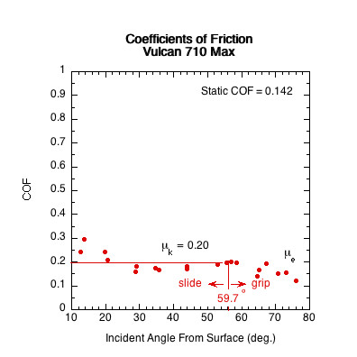
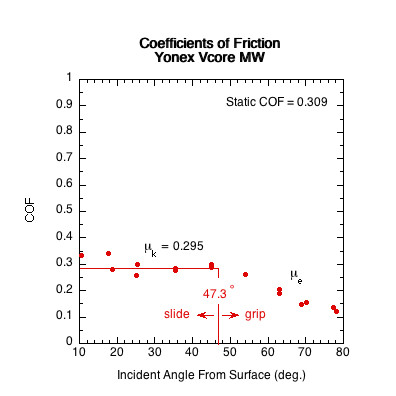
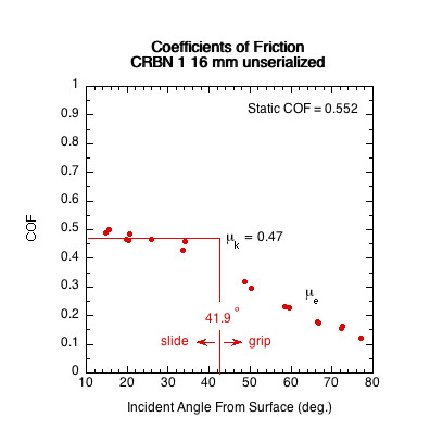
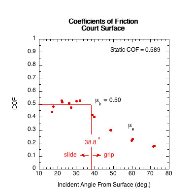
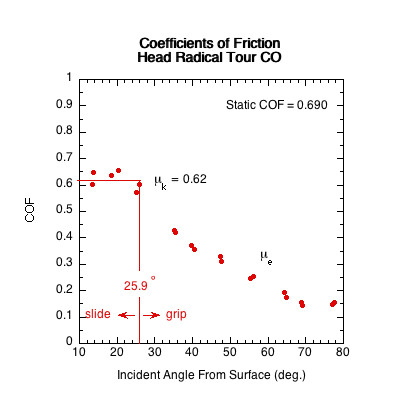
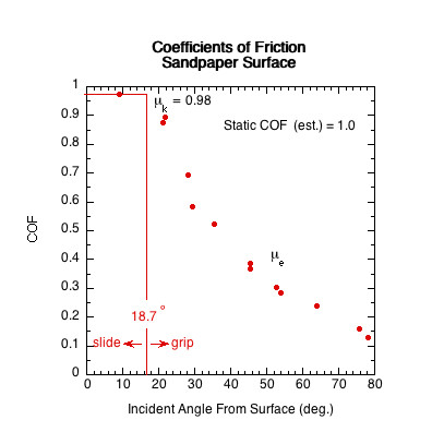
Figure 11 — Sliding COF (μk) Comparison. The sliding COF line is the average of all COF data points in the paddle's sliding range. In the sliding range, sliding COF is independent of velocity and angle and essentially does not vary.
5. Conclusion
All paddles will generate the same spin at all impact angles where their gripping ranges overlap (the range of angles over which maximum friction-induced spin is achieved). Paddles with higher static COF will have wider gripping ranges. At any given impact angle, a paddle that grips the ball at that angle will produce more spin than one that does not. If the incident and linear contact velocities are in opposite directions, all surfaces tend to grip the ball and there is no difference between paddles in spin production. If the incident contact velocities are in the same direction, then paddles with higher static COF will grip over a wider range of impact angles. However, almost all paddles grip above 60 degrees from the surface and most grip above 45 degrees from the surface. That is significant because most strokes impact the ball at more than 45 degrees from the surface. So, for almost all pickleball impacts, all paddles will produce about the same spin. When a player feels one racket produces more spin than another, it is most likely due to the speed, spin, and angle of the ball sent by the opponent, or the player can swing faster or steeper with a particular racket or against a particular style of player. It is not because of the racket surface roughness.
That being the case, having a maximum friction rule for approved paddles seems unnecessary and hindering of innovation. The gripping characteristics are important to feel of a paddle even if not to relative spin production over the range of impact angles hit by most players.
6. References
[1] R. Cross and C. Lindsey, "Spin and String Surface Roughness", https://twu.tennis-warehouse.com/learning_center/spinandfriction.php
[2] R. Cross and C. Lindsey, "Which Strings generate the Most Spin?", https://twu.tennis-warehouse.com/learning_center/spinexperiment.php.
[3] R. Cross, "Oblique Impact of a Steel Ball," Powder Technology 351, 282-290 (2019).