INTRODUCTION
If you drop a ball straight down onto the floor with no spin, it will bounce straight up with no spin — at least most of the time. Sometimes it will bounce just a tiny bit to one side or another and with just enough spin to see. That could be because of a slight bump, imperfection, hole, or slope in the surface, imperceptible to us but readily apparent to the ball. If the ball fell from a greater height, it would squash and spread out, and perhaps smooth out the "bump-effect" over a larger area and bounce straight up. On the other hand, the ball might not be quite spherical or may not recover its shape after bounces, and it will therefore sometimes bounce a bit askew.
If you drop a ball on the edge of a flat surface such that its center of mass (CM) is just a bit inboard of the edge, it will bounce straight up. If the center of mass is outboard of the edge, then it will fly off at almost any angle depending on how far outboard the CM was at impact. The ball will also have a great deal of spin. This is the "edge-effect".
Stringbeds are bumpy. They have many edges (the individual strings). The bumpiness seen by the ball will depend on the gauge and string pattern. This depends on impact location. In the center of the strings the pattern is tighter and equally spaced. Towards the periphery the spaces get progressively wider so one half of the ball might see a different landing pattern than the other half — i.e., more compact on one side and more open on the other. Presumably, the compact side will be stiffer than the open side.
The degree of bumpiness also depends on the size of the ball. If you drop a golf ball onto a tennis racquet, especially towards the periphery, there is no predicting in what direction the ball might bounce. The ball does not squash much and the impact contact area is almost always unbalanced in terms of the number of strings pushing up on each half of the ball. A much larger, heavier ball than a tennis ball would hardly notice any of these surface variations as it would spread out over a much larger area tending to equalize or hide the effects.
There is another effect that occurs for impacts toward the periphery — the "short-side effect" (also known as the "drum-effect"). When a string is hit, it stretches. On a typical tennis hit the perpendicular string deflection might be an inch. If this occurs in the middle of the string, then each half of the string will stretch the same amount to get to a one-inch deflection. If the impact occurs three inches from the frame, then the deflection will still be about an inch, but the short side of the string (the side closest to the frame) will have to stretch more compared to its distance to the frame than the other long side will stretch compared to its distance to the frame on the opposite side. The short side section of string will therefore be stiffer, bend at a greater angle, and form an incline of sorts directing the ball toward the center of the racquet away from the frame at the periphery.
We see in these examples not only real bumps, inclines, holes, and edges, but also what amounts to an effective edge. This is due to a difference in stiffness between adjacent strings. This leads to one side of the impacting ball to have a soft landing and the other side to have a hard landing. Such an unbalanced landing can effect the rebound angle and spin. Usually, these effects seem to be random and beyond our control. But the question is can we engineer these effects into a racquet in a manner that produces intentional rather than random rebounds?
First, we want to see these effects in action. Movie Screens 1-4 show edge bounces with varying degrees of rebound angle and spin. The magnitude of the angle and spin depends on location of the center of mass over the edge. If it is straight above the edge or over the table, there is no rebound angle or spin. Spin and angle increase the further out from the edge is a line dropped vertically from the CM.
Video 1
Edge Bounce Straight Up, No Spin
Movie Screen 1 — The ball's center of mass is located inboard from the edge over the table. The bounce is perpendicular to the table and without spin.
(Note: Use "double-arrow" movie controls for frame-by-frame play.)
Video 2
Small Angle, Low Spin Edge Bounce
Movie Screen 2 — The CM is just to the left of the edge so the bounce angle and spin rate are both small.
(Note: Use "double-arrow" movie controls for frame-by-frame play.)
Video 3
Medium Angle, Medium Spin Edge Bounce
Movie Screen 3 — The CM lines up a bit further to the left of the edge resulting in a larger rebound angle and spin.
(Note: Use "double-arrow" movie controls for frame-by-frame play.)
Video 4
Large Angle, High Spin Edge Bounce
Movie Screen 4 — The CM is far to the left of the edge and rebound angle and spin are much greater.
(Note: Use "double-arrow" movie controls for frame-by-frame play.)
None of those bounces are surprising. However this type of edge impact is not what we see in tennis. In a stringbed there are other strings underneath each half the ball tending to equalize forces and torques on each side — there is no real physical edge. Can we create a simulated or effective edge? We placed two foam squares of the same thickness but different stiffness next to each other. When we bounce the ball on either alone, the bounce is straight up with no spin. If we bounce the ball on the intersection, the ball bounces with topspin away from the stiffer foam (Movie Screen 5). We have created a stiffness edge.
Video 5
Edge Bounce At
Intersection of Stiff and Soft Foams
Movie Screen 5 — Bounce from impact at the intersection of two surfaces of different stiffness is at an angle with topspin.
(Note: Use "double-arrow" movie controls for frame-by-frame play.)
In order to better simulate a stiffness edge, we built a rubber band "stringbed". Rubber bands were stretched, woven, and anchored in a rig to simulate a string pattern in a racquet. A stiffness edge was then created by adding a stiff bungy cord at various locations in the bed next to the softer rubber bands. By doing so, the ball could be made to rebound in any direction depending on which side of the stiffness edge is impacted. Movie Screen 6 shows one such bounce that would not occur for a rebound from a normal "edge-free" surface.
Video 6
Stiffness Edge Bounce With
Bungy Cord In Rubber Band Bed
Movie Screen 6 — One string in a rubber band stringbed that is much stiffer than the others will cause an angled, spinning bounce if the string is hit off center on either side of the ball. The stiff string (a bungy cord) can be seen between the third and fourth band from the right. This string acts as an edge within the stringbed.
(Note: Use "double-arrow" movie controls for frame-by-frame play.)
Movie Screen 7 shows another rubber band stringbed demonstrating the effect of a variable tension stringbed. Each rubber band increases in tension from left to right. Each band was stretched a different length (longest on right, shortest on left) and then tied off in the middle at equal lengths. A ball bouncing anywhere on the stringbed (except on the far right rubber band) will bounce to the left with counter-clockwise spin. The stiffer string will stretch less during impact creating an "edge" that pushes and spins the ball to the left.
Video 7
Variable Tension Rubber Band Bed
Movie Screen 7 — Moving left to right, each rubber band is stretched to a higher tension, causing a tension ramp. Upon impact, one half of the ball will be on the higher stiffness side of the ramp (or edge) and the other side on the low stiffness side of the ramp. The stiffer strings will create counter-clockwise torque and spin.
(Note: Use "double-arrow" movie controls for frame-by-frame play.)
EXPERIMENT
The examples above demonstrate the effectiveness of an edge-effect at influencing rebound angle and spin. To test this effect in tennis racquets, we strung two racquets. The racquets were identical. Each had an 18 mains x 20 crosses string pattern and was strung with polyester. This closed pattern was chosen to equalize the number and spacing of strings across the contact area of the impact. One racquet was strung to simulate an edge effect or even a "ramp" effect. The center two mains were tensioned to 60 lb with each adjacent main decreasing in tension by 5 lbs, with the last string at the periphery at 20 lb on each half of the racquet. The cross strings were all tensioned at 50 lb. We will call this the "variable tension pattern" and it is similar in concept to the rubber band bed in Movie Screen 7 (the pattern is shown in Figure 2). The second racquet was strung normally at 50 lb for all strings (referred to as the "single tension pattern"). Balls were fired from a ball machine at 18 m/s and were aimed to hit between 3 and 9 o'clock on the stringbed at a 90 degree angle with no spin. Coordinate axes are shown dividing the stringbed into halves, from herein referred to as "top half of the racquet" and "bottom half of the racquet". The experiment setup is shown in Figure 1.
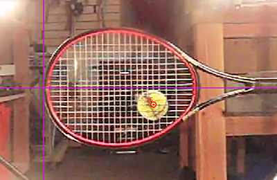
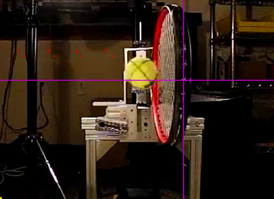
Figure 1 — Experiment setup: Back camera (a), side camera (b). Nominal topspin, backspin and sidespin = 0 and nominal vertical and horizontal impact angles = 90 degrees. Videos shot at 300 fps. The back camera measured impact location and the side measured incident and rebound velocity, spin, and angle.
Perpendicular, no spin impacts were chosen because we want to see the affect of the variable tension pattern independent of any effects caused by incident spin or angle. The effect of racquet twist on spin could not be controlled for but it could be accounted for. Since the racquets were identical except for string pattern, the effect of twisting on spin would be the same for impacts at the same location on each racquet, and any differences would thus be attributable to the string pattern. Any effects that we see will be very small because we are, so to speak, trying to create spin out of thin air. Perpendicular, no spin impacts upon a flat, stationary surface usually result in perpendicular, no spin rebounds. So, if we do find extra spin, the question for a future experiment would be how much, if any, can the effect be magnified by altering the incident ball and racquet parameters?
Due to variances in the launch device, the average incident angle = 0.16 degrees (upward), spin = 107.5 rpm (11.3 rad/s) counter-clockwise (backspin onto the strings), and the average contact velocity was 0.93 mph (0.42 m/s). Contact velocity (Vc) is the sum of the rotational and tangential linear speeds to the stringbed. For all impacts Vc was positive (upward on the stringbed). Friction acts opposite to the direction of Vc, so for all impacts friction acted to change the spin from counter-clockwise to clockwise and to push the rebound angle downward to the ground. This complicates the analysis, but fortunately these variances are smaller than the effects we are looking for. Figure 2 illustrates the incident conditions and the variable tension pattern.
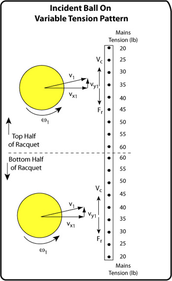
Figure 2 — Incident velocities are shown where v1 = incident velocity, vx1 = perpendicular velocity, vy1 is the tangential incident velocity and ω1 = incident spin. The tension on each main string is indicated. On the top half, the higher tension strings are on the lower side of the contact area, and on the bottom half of the racquet, the higher tension strings are on the upper half of the contact area.
Unless the ball hits on the center two mains, the force on one side of the ball was always more than on the other due to the variable tensions. On the bottom half of the racquet, the stiffer strings were on the top half of the contact area, increasing counter-clockwise spin. On the top half of the racquet, the stiffer strings were on the bottom half of the contact area, increasing clockwise spin. The force exerted by the stiff side strings either worked in the same or opposite direction as the friction force. In the top half, friction and stiff-side forces both acted to increase clockwise backspin. In the bottom half, friction acted to decrease counter-clockwise spin while the stiff-side force acted to increase it.
RESULTS
Figure 1 shows a comparison of the percent change in spin (100 x (ω2 - ω1) / ω1) for the variable tension pattern vs the single tension pattern. Percent change in spin is used because the magnitude of change in spin is dependent on the magnitude of the incident spin. Calculating the percentage change normalizes the data to comparable magnitudes. Simply reporting final rebound spins does not tell us what was changing during the interaction.
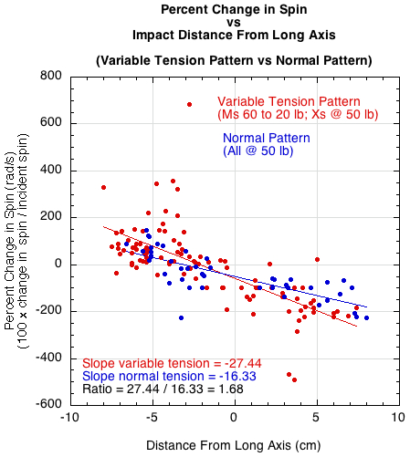
Figure 1 — The percent change in spin during impact vs the distance of impact from the long axis for both a variable tension pattern (red) and a single tension pattern (blue). The top half of the racquet is the positive x-axis values and the lower half the negative x-axis values. Topspin is the positive y-axis values and backspin the negative y-axis values.
The curve fit for the variable tension pattern is about 1.7 times steeper than that for the normal single tension pattern. The variable tension pattern produces both more backspin and topspin — the top-half of the racquet producing mostly backspin and the bottom half mostly topspin.
Ideally, all impacts would have been perpendicular with no spin. In that case, any change in the angle or spin would be due solely to normal force offset distance (D). The normal force (FN) is the force perpendicular to the surface due to the collision. The normal reaction force is the equal and opposite opposing force. The normal force offset is the distance in front or behind the center of mass (CM) that the line of action of the normal reaction force acts. Normally the offset can be influenced by incident spin, angle and impact location. For a ball dropped straight onto a flat, hard, solid surface, FN acts through the CM. If the ball hits at an angle, the bottom of the ball first slides and then grips the surface. The top of the ball will continue forward and downward, as when the front of a car lunges forward and downward when you apply the brakes. This action moves FN forward in front of the CM. The reaction force then pushes up in front of the CM, creating a backspin torque. The same thing happens if a ball with spin drops perpendicular to the surface. The ball will spin into the surface on one side and away from the surface on the other, moving FN to the side of the ball spinning into the surface.
The normal force offset can also be affected by racquet twist due to impact location. Impacts close to the long axis don't result in much twist whereas impacts near the periphery twist much more. Twisting moves the reaction force toward one side of the ball or the other. In the top half of the racquet, the stringbed will twist backward (clockwise in this experiment), moving the strings and the offset away from the top of the contact area and under the bottom of the contact area. The opposite occurs for impact in the bottom half — as the racquet twists backward (counter-clockwise in this experiment), the strings and the offset move into the top of the ball contact area and away from the bottom. The amount the offset shifts will depend on the distance of the impact from the long axis.
This experiment adds another factor that influences the location of the offset — FN can move according to an imbalance in tension/stiffness across the impact contact area. This imbalance can be due either to differences in tension or length of strings across the contact area. This imbalance is what we address below.
Normal force offset can be calculated from the equation FR – ND = Icmdω/dt, where F is the friction force, R the radius of the ball (33 mm), N the normal force, D the normal force offset, Icm = αmR2 is the moment of inertia of the ball about an axis through its center of mass and ω the angular velocity. For a tennis ball, α= 0.55.
The graph in Figure 2 shows the normal force offset for each impact in the bottom and top halves of the racquet. Usually, the offset location will be on the side of the ball in the direction of travel (the upward, positive, side for all impacts here), unless other factors influence it, such as variable tensions. For the variable tension pattern, the offset was positive in the bottom and mostly negative in the top. That means that the normal reaction force acted to increase CCW spin in the bottom half of the racquet and CW spin in the top half. For the single tension pattern, the offset was primarily positive in each half of the racquet, acting to increase CCW spin.
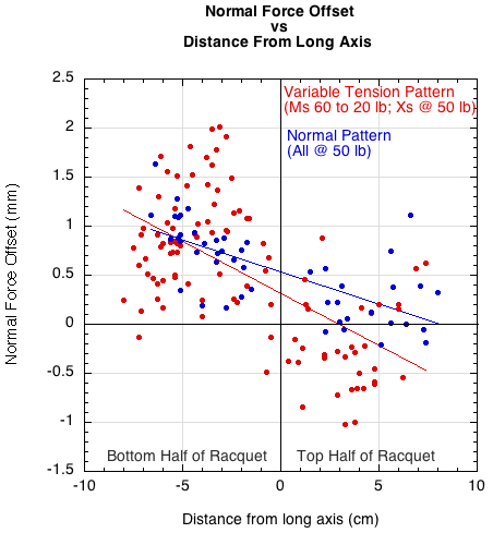
Figure 2 — Normal force offset vs distance from long axis in top and bottom halves of racquet. The offset was positive (top half of contact area) for impacts in the bottom half of the racquet and mostly negative (bottom half of contact area) in the top half of the racquet.
Figure 2 tells us that if the offset is positive in the bottom half of the racquet and negative in the top half, then we will see a generalized rebound spin model as seen in Figure 3.
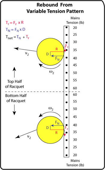
Figure 3 — Rebound Spins: Friction and normal force torques affecting spin in each half of the racquet. The offset is located on the side of the contact area that has the greater tensions.
It is interesting to see how all the forces come together to create the final spin result. The friction force is much smaller than the normal force (Figure 4).
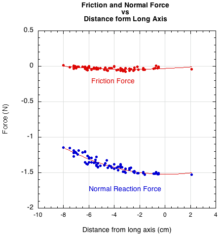
Figure 4 — Friction and normal force at each impact point. The normal force is much greater than the friction force.
But it is not the force alone that determines spin. It is also the length of the so-called moment arm or lever arm against which the force is applied that is important. Torque, which causes spin, is given by Fs where F is the force and s the perpendicular distance of the line of force to the CM (the moment arm). So, in Figure 3, the normal force torque will be FND and the friction torque will be FrR, where D and R are substituted for s. Though Fr is much less than FN, R (33 mm) is much greater than D (average around .5 mm), so the two torques are very nearly equal but opposite as shown in Figure 5.
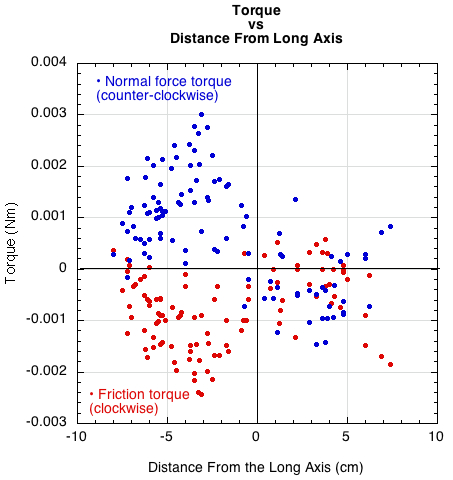
Figure 5 — Friction and normal torque at each impact point. Torque due to friction is given by Tr = FrR and torque due to normal force offset is given by TD = FND.
Figure 6 shows the net torque as a result of summing Tr and TD for each impact in Figure 5. The net torque tends to be greater in both halves of the racquet for the variable tension pattern compared to the single tension pattern.
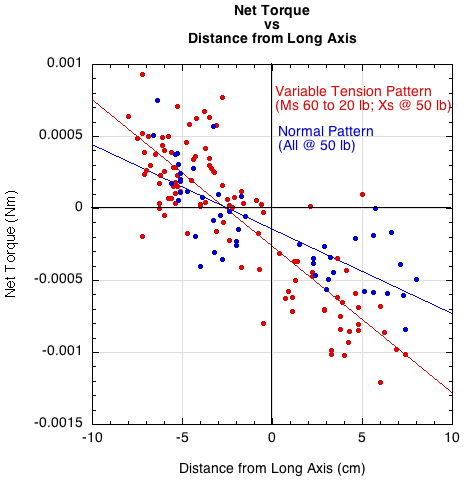
Figure 6 — Net torque vs distance from long axis for both variable tension pattern (red) and the fixed tension pattern (blue).
Figure 7 shows the change in spin vs the net torque. The variable tension pattern created the most positive and negative torque and most the most change in spin, whether topspin and backspin, as shown by both ends of the curve being red (i.e., the variable tension pattern).
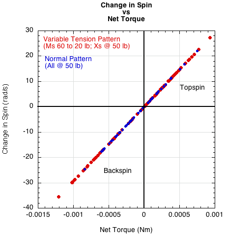
Figure 7 — Change in spin vs net torque for the variable tension and single tension patterns.
For brevity and simplicity, our main concern here has only been spin. However, the rebound parmeters of interest are speed, spin, and angle. So, for the sake of completeness, ACOR (ratio of perpendicular rebound velocity to perpendicular incident velocity) and change in angle are presented in Figures 8 and 9.
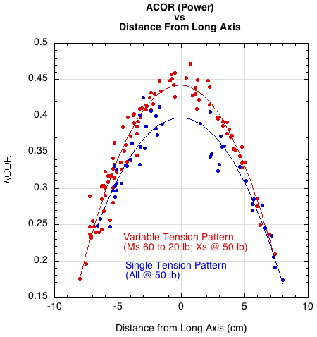
Figure 8 — ACOR vs distance from long axis for variable and single tension patterns.
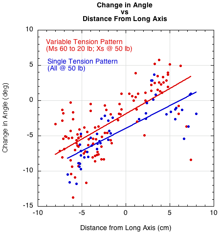
Figure 9 — Change in angle vs distance from long axis for variable and single tension patterns.
CONCLUSION
The variable tension string pattern produced 1.7 times as much percentage change in spin as the single tension pattern. Granted the magnitudes of the spin values are small, but that is due to the restrictions of our input parameters. Furthermore, the ideal configuration of the variable tensions is yet to be determined. Would 10 lb variances between strings be better? Or would material differences between adjacent strings be better? What about reversing the tensions such that the middle two strings are 20 lb and each adjacent string increase 5 lb out to the periphery at 60 lb? And what if we use a more open pattern? Can cross string tension be variable also? How does cross string tension affect the variable main string tension? What happens when the strings slide and are pushed to one side of the ball or another during impact?
How much difference to expect in actual tennis playing remains to be determined. Will the effect be drowned out when hitting real shots with real incident speeds, angles and spins? How difficult is stringing a variable tension pattern?