INTRODUCTION
The parameters for an "official" ball are prescribed by the International Tennis Federation (ITF) as shown in Table 1.
| Table 1 ITF Tennis Ball Specifications | ||||
|---|---|---|---|---|
| Type 1 (Fast) | Type 2 (Medium) | Type 3 (Slow) | High Altitude | |
| Weight | 56-59.4 g (1.975-2.095 oz) |
56-59.4 g (1.975-2.095 oz) |
56-59.4 g (1.975-2.095 oz) |
56-59.4 g (1.975-2.095 oz) |
| Size | 6.54-6.86 cm (2.57-2.76 in) |
6.54-6.86 cm (2.57-2.76 in) |
7.0-7.3 cm (2.76-2.87 in) |
6.54-6.86 cm (2.57-2.76 in) |
| Rebound Dropped From 100 Inches |
138-151 cm (54-60 in) |
135-147 cm (53-58 in) |
135-147 cm (53-58 in) |
122-135 cm (48-53 in) |
| Forward Deformation |
0.56-0.74 cm (0.229-0.291 in) |
0.56-0.74 cm (0.229-0.291 in) |
0.56-0.74 cm (0.229-0.291 in) |
0.56-0.74 cm (0.229-0.291 in) |
| Return Deformation |
0.74-1.08 cm (0.291-0.425 in) |
0.80-1.08 cm (0.315-0.425 in) |
0.80-1.08 cm (0.315-0.425 in) |
0.80-1.08 cm (0.315-0.425 in) |
Table 1 — ITF Ball Specifications.
The most popular balls are Type 2 balls, and all balls tested were Type 2, except one high altitude ball.
The first three specifications in Table 1 are obvious but forward and return deformation are not. The forward and return deformations are measurements of ball stiffness during compression and decompression. The ball is slowly compressed (i.e., not dynamically as in a bounce) to a force of 18 lbs, and the deformation is measured (forward deformation). The force is increased until compression equals an inch. The force is then decreased back back to 18 pounds and deformation is again recorded (return deformation). The ball stiffness is defined as the force (18 lb) divided by the deformation. There is both a forward and return stiffness. To be approved, forward stiffness would be between 61.8 lb/in and 78.6 lb/in and return stiffness would be between 42.4 lb/in and 114.2 lb/in. The stiffness is defined as the force in pounds necessary to deform the ball 1 inch — i.e., k=F/x, where k is stiffness, F the force, and x the deformation. Balls are stiffer during compression than they are during decompression.
The ITF's goal is to certify uniformity and consistency of performance. To do so, testing methods, procedures, equipment, and conditions (temperature, humidity, atmospheric pressure) are rigidly prescribed. All balls must be pre-compressed 1 inch on each axis before testing, and each axis is tested. Because we are using approved balls for our test, we know they all should meet the above requirements. But, except for the bounce tests, these requirements are not performance based. We wanted to compare ball behaviors under dynamic impact conditions. We developed a test device and procedure to do just that.
EXPERIMENT
Balls were placed on a steel surface and secured with double sided tape. A drop weight with a mass of 4.3 kg was dropped from a height of 148-149 mm above the top of the ball. The drop weight was instrumented with a force gauge, accelerometer, and LVDT (linear variable differential transformer). These instruments allowed measurement of force, deformation, dwell time, speed, energy, stiffness, and load rates throughout the impact.
The ITF drop test is performed from a height of 100 inches, which results in a drop speed of 16 mph and an energy at impact of about 0.083 Joules (J). The TWU tests are preformed at considerably higher energies. The drop weight collides with the ball at 1.7 m/s with an energy of about 6.7 J. Such an impact compresses the ball 1.4-1.6 inches, or about 54-62% of its diameter. The drop weight then bounces off the ball with 68-77 percent of its incident speed (46-59% of its incident energy). The impact duration was between 65 and 71 ms. This is longer than the 5-8 ms ball bounce from a solid surface or racquet. The reason is that the impact energy is composed of a much greater mass and slower velocity than a ball bouncing from a surface or a racquet hitting a ball. An impact of 6.7 J is what you would get by dropping a ball from 39 feet or hitting a serve with a racquet moving at 20 mph in the center of the racquet (e.g., effective mass of 171 g), which would result in a serve of only 26 mph. However, the greater mass of the drop weight and the longer impact duration serve to stress the ball as much or more than a 100 mph serve, given the compression of over half of its original diameter. Video 1 shows a typical impact delivered by the apparatus.
Video 1
Ball Impact Test
Fourteen models of balls were tested. Each model was given an identification number and each ball within a can given a letter ID. Table 2 presents a list of balls tested.
| Table 2 Balls Tested | |||||
|---|---|---|---|---|---|
| ID Number | Brand | Model | Duty | Pressurized | High Altitude |
| 1 | Dunlop | Grand Prix | Extra | Yes | No |
| 2 | Dunlop | ATP Championship | Extra | Yes | No |
| 3 | Dunlop | ATP | Extra | Yes | No |
| 4 | Dunlop | Championship Hardcourt | Extra | Yes | No |
| 5 | Penn | Championship | Regular | Yes | No |
| 6 | Penn | Championship | Extra | Yes | No |
| 7 | Penn | Tour | Extra | Yes | No |
| 8 | Pro Penn | Marathon | Extra | Yes | No |
| 9 | Wilson | US Open | Extra | Yes | No |
| 10 | Wilson | US Open | Regular | Yes | No |
| 11 | Wilson | Championship | Extra | Yes | No |
| 12 | Tecnifibre | Court | Extra | Yes | No |
| 13 | Wilson | Triniti | Extra | Partial | No |
| 14 | Dunlop | ATP Championship | Extra | Yes | Yes |
Table 2 — Balls Tested.
A number of tests were preformed on all balls over a number of days. On day 1, all balls were impacted once on a random axis and measurements taken. On days 2, 3, and 9 after opening, each ball was impacted and measured once on the same axis as that of day 1. On day 10, one ball from each can was impacted 5 times on each of 3 perpendicular axes and measurements taken on impact 1 and 5 for each axis. A final test was performed using new cans but with only 8 models. This test varied the mass of the drop weight to alter the impact energy. The aim was not to compare balls but to see if the energy return would change depending on the incident energy. In other words, would greater deformation lead to greater loss in energy?
These tests evolved over the days due to a peculiarity observed on the measurements of days 2-9. We expected to observe a decrease in energy return as internal ball pressure decreased due to air leakage. Instead, energy return increased on each of days 1-9 and then, for several balls, decreased on day 10. It was this phenomenon that prompted the three axes tests to see what was going on.
RESULTS
Day 1 Testing
The primary areas of interest are energy return and bounce speed, performance durability, and feel. Figure 1 compares the percentage of energy return for each ball and Figure 2 shows the ratio of the outgoing to incident speeds of the drop weight (the ball is secured to the surface and remains stationary throughout). That ratio is known as the coefficient of restitution (COR).
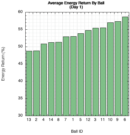
Figure 1 — Average energy return of all three balls per can immediately after opening.
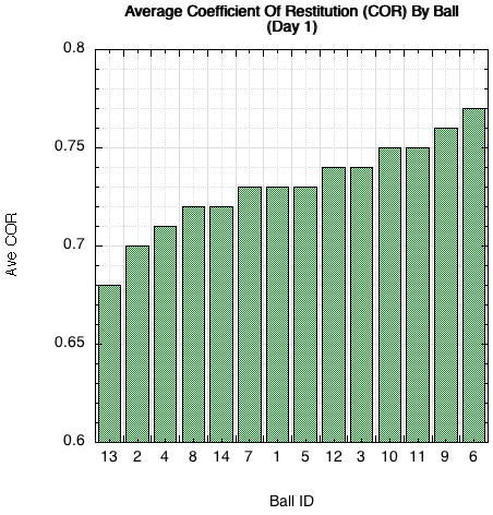
Figure 2 — Average COR of all three balls per can immediately after opening. COR is the ratio of outgoing to incoming velocity.
Energy return and COR are different ways of presenting the same thing — the speed and liveliness of the ball. Energy return and energy loss are two sides of the same coin. During impact, the drop weight's kinetic energy (energy of motion) is transformed into elastic energy in the compressed ball. But during this process, some energy is lost due primarily to internal friction and vibration in the ball. The stiff aluminum drop weight does not deform, so it loses little energy (except the apparatus itself loses a bit in vibration and friction of sliding components). This energy loss can be tracked during impact. The ratio of decompression time to compression time ("recovery ratio") intuitively illustrates the process. In a perfect world, the time, force, and energy to eject the drop weight would all be the same as it takes to stop it. However, in an energy-loss world where energy leaks out of the system, there is less energy and force available during ejection, so it takes longer to eject the drop weight than it takes to stop it. Further, it takes a few ms to completely recover shape after drop weight ejection. In the real world, the recovery ratio is always greater than 1. Figure 3 shows this relationship for all balls on day 1.
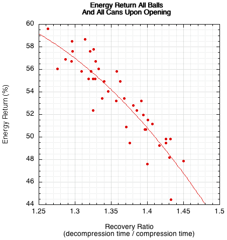
Figure 3 — Energy return vs recovery ratio. The recovery ratio is the ratio of the decompression to the compression durations. As the ratio increases, the energy return decreases. In other words, the longer the decompression to compression time, the greater the energy loss.
The ITF's "forward" and "return deformation" is a similar indicator of energy loss, but the semi-static (i.e., continuous force instead of impact force) test procedure makes it less intuitive and less synonymous with actual play. If you divide the ITF's return deformation spec by the forward deformation spec at each end of the ranges given in Table 1 (measured in inches), you will get 1.37 (.315/.229) and 1.46 (.425/.291). The overlap and agreement with Figure 3 is evident. However, at the extreme, the ratio of the maximum allowed return deformation (.425) to the allowed minimum forward deformation (.229) would be 1.86 (.425/.229). Extrapolating from the graph in Figure 3, that would barely bounce at all, even though the specification would theoretically allow it.
For most instances, energy return and COR are properties that are transferable between variable impact conditions. They are not dependent on the energy of impact. If a ball has a COR of 0.75 (56% energy return) under one set of conditions, it will most likely have nearly the same under another set, the only difference being due to random events such as the landing axis.
Besides bounce liveliness, players are also concerned with the feel of impact. "Feel" depends on 4 factors: the peak force, amount of compression, the load rate of the force, and the ball stiffness. All these factors depend on each other, but the best illustration of their dependency is shown in Figure 4 showing how stiffness increases as the load rate increases. Load rate is given by force / time to peak force. Stiffness is given as force / deformation.
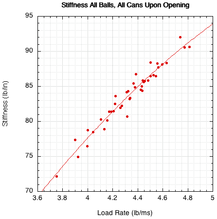
Figure 4 — Stiffness of all balls upon can opening vs the load rate.
The comparison of the components of Figure 3 (force, deformation, stiffness and load rate) is shown in Figure 5 (stiffness) and Figure 6 (load rate) for all balls.
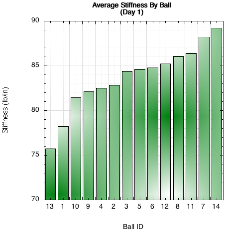
Figure 5 — Comparison of average stiffness for each can of balls on day 1.
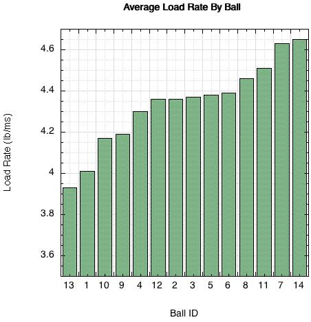
Figure 6 — Comparison of average load rate for each can of balls on day 1.
It is important to note that stiffness is a moving target. Stiffness is not a singular identifying property of a ball. It changes with impact energy (which changes with mass or velocity). So you can't compare the stiffness of balls under different impact conditions. The measurements must be made under the same initial conditions. However, the qualitative differences between balls will persist between impact conditions. If ball A is stiffer than ball B at one set of conditions, it will also be stiffer under other conditions. As indicated in the Introduction, the ITF forward stiffness is measured using a slow compression and must be between 61.8 nd 78.6 lb/in. This compares to 75-90 lb/in measured in our impact tests in Figure 5. The comparative results will be the same even though the numbers will be different.
Load rate (Figure 6) is important to what the player feels at impact. A high load rate indicates a high force for a short amount of time and a low rate indicates lower force for a longer time. The first would most likely indicate liveliness to a player and the latter either sluggishness or control.
Surprisingly, the total difference in deformation during impact between balls is only about 0.1 inch (2.5 mm), as shown in Figure 7.
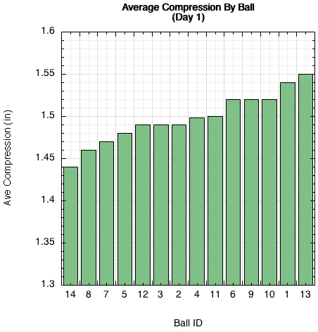
Figure 7 — Comparison of impact deformation for each can of balls on day 1.
Day 1-10 Testing — Performance Durability
As noted above, the procedure designed to test for the rate of decline in energy return turned out to be a test for the opposite — the increase in energy return. Energy return increased for most balls on days 1-9, and then some began to display decreases on day 10. This result is shown in Figure 8.
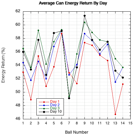
Figure 8 — Average energy return per can for days 1-10. Most balls on most days increased in energy return when impacted on the same axis each day. Only ball 7 decreased each day.
For most balls, the plotted points increase vertically in the order of red, blue, green, black. There are a few exceptions, but the overall trend tends to reassert itself when an anomalous measurement occurs — except ball 7, which behaved exactly as one would expect, with energy return decreasing each day. Day 10, shown in larger black symbols is first day that some balls reverse this trend.
Why the energy return increase? All balls were impacted along the same axis each day. Perhaps that stiffened the ball along that axis and/or left the ball in a pre-compressed condition after each impact. Both hypotheses were true, as shown below.
Day 10 Testing — Shape and Bounce Asymmetry
First, Figure 9 shows that stiffness did tend to increase each day for almost all balls.
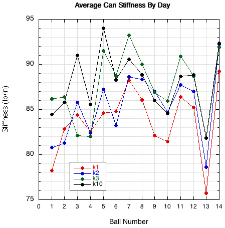
Figure 9 — Average stiffness per can for days 1-10. Stiffness increased most days for most balls, except day 10 which tended to be less stiff than the previous day.
It was then hypothesized that the ball never fully recovers it dimensions and remains set in a pre-compressed state after each impact. To investigate, the following procedure was established: impact the x axis 5 times and measure impact 1 and 5. Then, rotate 90 degrees and do the same for the y and then the z axis. Then rotate back to the x axis and measure impacts 1 and 2. This last rotation was to see if only one, not five, impacts were adequate to "pre-set" the ball. The results showed that the diameter decreased in the direction of impact. So the first hit on each axis decreased the diameter, increased the stiffness, and increased the energy return for the next impact on the same axis. When the ball was rotated to the next perpendicular axis, the diameter would then be larger (having expanded due to previous hits on the previous perpendicular axis). So, on the first hit the stiffness and energy return were less, upon which they increased on successive hits. This pattern continued for all axes. A typical series is shown for ball 8 in Figure 10.
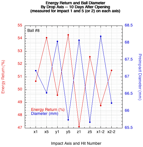
Figure 10 — Energy return and diameter vs impact axis and impact number. The letter is the axis and the number the impact. The "-2" indicates impacts on the x axis a second time. In all cases, the ball did not completely recover its diameter after impact. This "pre-compression" resulted in stiffer impacts with more energy return for successive hits on the same axis. Rotating to a perpendicular axis resulted in a softer impact and decreased energy return for the first impact and then stiffer and bouncier for successive impacts. The cycle continues for each change in impact axis.
As diameter decreases due to compression pre-set, energy return increases, and as diameter increases due to change in axis, energy return decreases.
The ball was not removed or manipulated in any way between impacts. The measurement of pre-impact diameter was accomplished simply by recording the drop weight drop distance before a force was triggered at impact and comparing it to the previous impact recording.
So, the procedure designed to demonstrate decline in performance ended up being a test demonstrating bounce variability and randomness instead. Depending on the ball's impact history, each bounce may be different than the last, even if the impact angle, speed, and spin are the same.
Variable Impact Mass Testing
Eight separate cans of balls were used for testing the effect of different drop masses. The three masses used were 2.1 kg, 4.3 kg, and 7.1 kg. The resulting energy of each impact was 3, 6.3, and 10.4 Joules. Only one ball per can was tested and it was impacted on the same axis for each one-time hit of each mass. Figure 11 shows the result for each ball and Figure 12 shows the average for all balls at all masses.
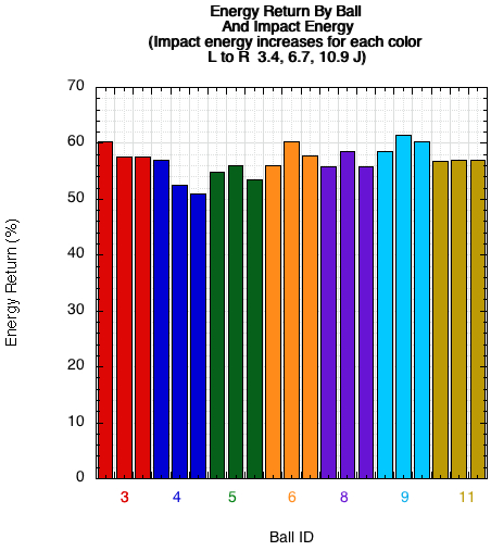
Figure 11 — Energy return by ball vs impact energy.
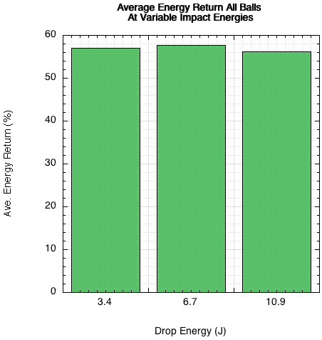
Figure 12 — Average energy return for all balls vs impact energy. Changes in impact energy did not influence the energy return.
Though this is not a statistically valid sample, it shows that most likely, over the range of impact energy tested, that there is no trend other than small random variance. If rebound asymmetry and added impact energies simultaneously affect the results, they may cancel each other and hide a trend. That, however, is test for another day. That being said, the relative performance comparisons between balls presented above should be valid across a varying range of impact energy. It should be noted that for groundstrokes, the impact energy is simply that of free fall from the apex of the trajectory. The ball simply drops and the range of impact energies are fairly small. However, for serves, overheads, and volleys, there is added downward velocity due to the downward launch angle from the racquet. And, of course, for a racquet-ball collision, there is a much larger range of possible energies.
CONCLUSION
There are differences in balls that can be measured, seen, and felt. The range of differences is limited by the rules of tennis, but the variability is enough to affect one's play.
Other things learned, confirmed, or suspected were that ball bounce is variable even under identical impact parameters, energy return increases if impacts are preformed on the same axis, balls never truly regain their original shape, shape influences bounce speed, and percent energy return is independent of the magnitude of the impact energy.