1. INTRODUCTION
For all the talk and advertising surrounding kick points, it is difficult to find a consistent and meaningful definition. The most frequently cited definition is that it is the point along the stick that flexes most during a shot. As such, it is generally categorized into three types: mid, low, and variable. The mid-kick point flexes most in the middle and has the most power, the low kick point flexes most in the lower third of the stick and is good for quick but less powerful shots, and the variable kick point is supposed to adapt itself to the shot.
This definition was not entirely satisfying. First, both calculations (Flex of a Hockey Stick — the Kick Point) and experiments showed that the maximum bending always occurs near the middle of the stick unless extreme, impractical methods were used. Two other alternatives presented themselves: did people really mean the "most flexible point" or did they mean the location closest to the blade where the stick begins to bend?
With regard to the first option — kick point being the most flexible point — we measured the flex variation of 13 high performance sticks over the length of the stick (See Hockey Stick Flex Profiles). That showed that almost all sticks are softest at the top end and stiffest in middle or blade end. So that did not match up with the stick's designation as "mid" or "low" kick point.
So, perhaps it was the last definition: the kick point being the point on the distal end of the stick where bending begins. When a stick bends, a segment on each end remains almost straight. The length of that segment might lead us to the kick point.
2. EXPERIMENTAL ARRANGEMENT
Two variations of a pendulum mechanism were built to simulate the swing of a stick. In one variation, a bungee cord pulled the pendulum arm through contact with the puck (100 g brass weight), regulating a constant speed and force of contact. In the second variation, a pull-weight was used to pull the pendulum arm through contact. In addition, a sliding drop mass was attached to the stick. This mass slid down the stick as the pendulum dropped and was timed to "bottom-out" at "ice" contact. This added extra bending energy to the stick, just as a player does when leaning into the stick after ice contact. The drop mass landed on a spring that increased the duration of loading as the stick slid along the ice. Figure 1 shows the devices and Movie Screens 1 and 2 below show them in operation.
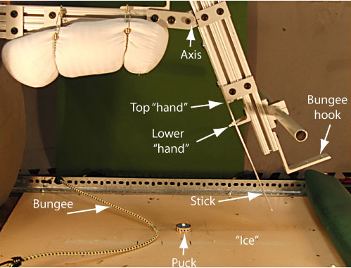
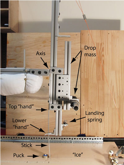
Figure 1 — Two experimental pendulum setups: bungee powered (top) and falling weight powered with drop mass to add bending force (bottom). In the bungee apparatus, the bungee hooks around the angle brace at the bottom of the pendulum. The pendulum is then pulled back, released, and the bungee pulls the pendulum forward through puck release. For the drop weight setup, a 5 lb weight is attached to the pull line at the top of the pendulum. The pendulum is raised to the "pendulum take back" stopper and the sliding drop mass is raised to the drop height stopper. The pendulum is released and the weight pulls the pendulum through puck release and the drop mass descends to the landing spring just after the stick makes table contact. The "lower hand" is shown in different positions in the photos.
Movie Screens 1 and 2 present the experimental setups in slow motion action.
Bungee Powered Stick
Movie Screen 1 — Bungee powered pendulum. The stick hits the table top ("ice"), slows, and bends before hitting the puck. It then bends more at puck contact. The combination of rotational and elastic energy drive the acceleration and release of the puck. Not all the energy goes into the puck as evidenced by the continued follow-through of the pendulum arm and the vibration of the stick. (Note: By using the forward and backward double arrow keys, you can go forward and backward a frame at a time.)
Pull Weight Stick With Drop Weight Loading
Movie Screen 2 — Drop Weight Mechanism. As in Movie Screen 1, the stick hits the ice and puck and bends, but the drop mass increases the bending. The drop mass descends as the pendulum rotates. At, or just after, ice contact, the drop mass contacts the spring and begins loading the stick for the next couple of frames. (Note: By using the forward and backward double arrow keys, you can go forward and backward a frame at a time.)
An aluminum beam (37 mm wide and 3 mm thick) was used as a stick. The beam was bolted to the pendulum and could be easily adjusted up and down to allow for different degrees of slapping and sliding along the table (referred to as the "ice") before hitting the puck. The stiffness of the stick was altered by attaching a second beam to the first with double sided tape. The length of the second beam was adjusted to either 46%, 62%, 66% or 100% of the length of the first beam. It extended from the top of the stick downward. Using these different length second beams, the stiffness could be altered either uniformly (using 100%-length beam), or variably (using the 46%-, 62%-, and 66%-length beams). The 66% length beam was also less stiff, being only 2 mm thick instead of 3mm — Figure 2 (66% length not shown).
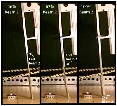
Figure 2 — Variable stiffness sticks. Variable stiffness sticks created by attaching a second aluminum beam (3 mm thick) to the first. Second beam sections were a percentage length of the first: 46% (left), 62% (middle) and 100% (right). The 66%-length (2 mm thick) beam is not shown.
The hand position was adjusted by sliding and tightening the angle brace labeled "lower hand" in Figure 1. The hand positions were located 22%, 31%, and 50% from the top of the stick (the "top hand"). In one instance the data also shows a hand position 74% from the top.
3. RESULTS AND DISCUSSION
Maximum Deflection — how does hand position and stiffness affect its location?
We measured the distance of the maximum bend point from the top of the aluminum stick in a number of situations by varying both the hand position and the flex profile for preloaded impacts with the puck:
- Single uniform stiffness and thickness (3 mm) aluminum bar in 4 hand positions: 74, 50, 31, and 22 percent from the top.
- Double uniform stiffness and thickness (6 mm) aluminum bar in 3 hand positions: 50, 31, and 22 percent from the top.
- 46% Double bar and 54% single bar with variable stiffness and thickness (6 mm to 3 mm) stick in 3 hand positions: 50, 31, and 22 percent from the top.
- 62% Double bar and 38% single bar with variable stiffness and thickness (6 mm to 3 mm) stick in 2 hand positions: 50 and 31 percent from the top.
- 66% Double bar and 34% single bar with variable stiffness and thickness (6 mm to 2 mm) stick in 3 hand positions: 50, 31, and 22 percent from the top.
The maximum bending point was found by projecting straight lines from the straight portions of the stick on each end. The maximum bending point is located opposite the intersection of these lines (Figures 3-7). Furthermore, where the stick begins to deviate from these straight lines might be our kick point. The results were as follows;
- The maximum deflection point followed the hand position but always remained more to the middle than the hand.
- The maximum deflection point follows the transition point between stick thicknesses.
- The maximum deflection point is influenced by the magnitude of stiffness variation on either side of the thickness transition point.
All these results are displayed in Table 3 and Figures 3-7. All distances are measured as percentages from the top of the stick.
| Table 3 Maximum Deflection Location vs Hand Location and Transition Point | |||||
| Stick Type (thickness bar #2) |
Transition Point From Top (% length) |
For Hand 74% From Top |
For Hand 50% From Top |
For Hand 31% From Top |
For Hand 22% From Top |
|---|---|---|---|---|---|
| 1xAlu | None | 57% | 50% | 42% | 33% |
| 2xAlu | None | 50% | 44% | 38% | |
| 1.46xAlu (3 mm) | 46% | 52% | 47% | 46% | |
| 1.62xAlu (3 mm) | 62% | 57% | 48% | ||
| 1.66xAlu (2 mm) | 66% | 73% | 67% | 65% | |
Table 3 — Maximum deflection vs hand position and stiffness.
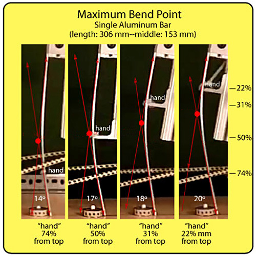
Figure 3 — Uniform 3mm thick stick: Maximum deflection follows the hand position but stays medial to the hand.
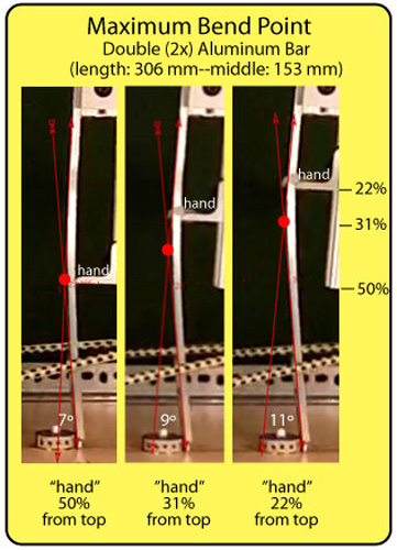
Figure 4 — Uniform 6mm thick stick: As with the single thickness stick, the maximum deflection follows the hand postion but it does not travel as far.
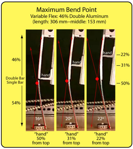
Figure 5 — Variable flex: 46% = 6 mm, 54% = 3 mm thickness: The maximum deflection stays very close to the transition point between 6 mm and 3mm thickness. What little movement there is follows the hand position. The relative invariance of max deflection point here is accentuated because the transition point is also very close to the middle of the stick.

Figure 6 — Variable flex: 62% = 6 mm, 38% = 3 mm thickness: The lower transition point shifts the range of maximum deflection variation toward the lower end of the stick.
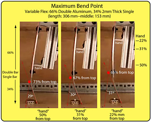
Figure 7 — Variable flex: 66% = 5 mm, 34% = 2 mm thickness: The slightly lower transition point and more radical variation in thickness at the transition point, lowers the kick point even further. The angles of deflection are greater here than Figures 7-10 because this test was performed on the drop mass pendulum while all the others were performed on the bungee pendulum. The drop mass adds more bending force to the stick.
Figures 3-7 indicate that given the right construction, stiffness, and flex points, manufacturers can move the point of maximum bend slightly up and down from the middle. This deviation follows the hand, especially for a uniform stiffness stick. It also follows the stiffness transition point. However, the radical change in stiffness used in the variable stiffness sticks would, however, never occur in real sticks. The goal of the experiment was to show, in principle, what can be done.
Though much of the literature on hockey sticks refers to the kick point as the point of maximum bending, our tests did not find this to be the case — the point of maximum bend is always close to the middle of the stick, does not move very much, and does not match very closely to advertised kick point locations. We instead took our cue from a definition given by A. Villasenor, et. al. [4]: the kick point is the "point along the shaft where the predominant bending begins." We visually determined the separation point of a straight line along the stick from the tip upward. The line separated from the stick where the bending began. Figure 8 shows the separation point.
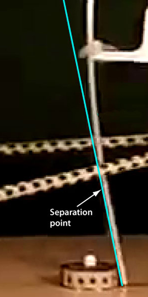
Figure 8 — Kick point as location where bending begins — The separation point is a visual approximation.
The distance of the separation point from the top of the stick was measured and calculated as a percentage of the stick's length from the top. This location more closely matches the kick point as designated by manufacturers (Table 4).
| Table 4 Bending Initiation Point (Kick Point) vs Hand Location and Transition Point | |||||
| Stick Type (thickness bar #2) |
Variable Stiffness Transition Point From Top (% length) |
KP % from top For Hand 50% From Top |
KP % from top For Hand 31% From Top |
KP % from top For Hand 22% From Top |
|
|---|---|---|---|---|---|
| 1xAlu | None | 68% | 64% | 59% | |
| 2xAlu | None | 68% | 64% | 57% | |
| 1.46xAlu (3 mm) | 46% | 74% | 69% | 69% | |
| 1.62xAlu (3 mm) | 62% | 75% | 72% | ||
Table 4 — Bending initiation point vs hand position and stiffness.
If we define this bending initiation point in the lower portion of the stick as the kick point, we can say the following:
- lower hand position = lower kick point
- lower stiffness transition point = lower kick point
- lower stiffness = lower kick point
Kick point defined in this way correlates well to the location on the stick of the kick point as designated by manufacturers for each stick. However, this is just the end point of maximum deflection. The maximum deflection point and the kick point are talking about the same bend. As such they are not different things and do not account for different performances or feel. A stick's kick point and maximum deflection point are just different ways of talking about the same performance. So the confusion of definition is a confusion in descriptions not of properties.
4. CONCLUSION
The kick point is a side effect of stiffness and hand position. As such, it is simply a convenient term to convey properties in marketing terms. Hand position and stiffness variation along the stick alter the maximum deflection point and with it the kick point. Overall stick stiffness is probably a more indicative property to relate to power and feel than trying to conceptualize in terms of kick points. Kick points are associated with power or release quickness, but these, as well as the kick point itself, are just the manifestations of stiffness (flex).
References
1. R. Anderson and L. Smith, “Experimental Characterization of Ice Hockey Sticks and Pucks,” Journal of ASTM International, 6(7), 1-8 (2009).
2. B. Kays and L. Smith, “Field Measurements of Ice Hockey Stick Performance and Player Motion,” Procedia Engineering 72, 563-568 (2014).
3. K.V. Lomond, R.A. Turcotte, and D.J. Pearsall, “Three-dimensional Analysis of Blade Contact in an Ice Hockey Slap Shot, in Relation to Player Skill,” ISEA Sports Engineering 101, 87-100 (2007).
4. A.Villasenor, R.A. Turcotte, and D.J. Pearsall, “Recoil Effect of the Ice Hockey Stick During a Slap Shot,” Journal of Applied Biomechanics 22, 202-211 (2006).
5. J.T. Worobets, J.C. Fairbairn, and D.J. Stefanyshyn, “The Influence of Shaft Stiffness on Potential Energy and Puck Speed During Wrist and Slap Shots in Ice Hockey,” ISEA Sports Engineering 9, 191-200 (2006).