ABSTRACT
Does Tennis String Affect Spin?
The affect on spin of altering the coefficient of friction between a string and a ball is examined. The coefficient of friction was increased by filing the string surface. Only the string surfaces that would contact the ball were filed. In this way, the friction between strings was not altered so that the mains could continue to slide unimpeded on the cross strings. A plexiglass frame was constructed to view the impact from the side and to measure all the ball and string parameters during contact. Stringbeds were constructed with and without cross strings in order to determine the nature of the string-to-ball interaction. In this manner, the forces and mechanisms involved in spin generation could be isolated and measured.
A primary objective was to see how increasing the coefficient of friction would affect the lateral movement of the string. In recent years it has been shown that lateral string movement produces extra spin during the "snap-back" phase of the impact. One of the most interesting discoveries of this study is that this "snap-back" is only half the story and is a partial misrepresentation of actual events.
Another interesting observation is that although splitting a reaction force into normal and friction forces is the best and easiest way to analyze torque and spin on flat and largely non-compliant surfaces, for single or multiple, unconnected strings, the most direct, intuitive, and visual technique is simply to observe the line of action of the force of each string on the ball.
It was found that higher COF strings produce more torque and spin early in the impact, but under certain circumstances may undo some of this at the end of impact due to a reversal of friction and torque. Friction reversal was most evident in stringbeds without crosses and thus exhibited minimal if any increase in spin in the filed condition compared to the unfiled. Stringbeds with crosses produced more spin with filed strings because friction was not reversed.
Movie Screen 1 shows a preview of the experiment in action. The line of action of the string force on the ball can be seen for each string in the no-crosses video. The video of the with-crosses stringbed shows this approach becomes more difficult as the stringbed gets stiffer, more incompressible, and the strings become more interconnected. This is when customary friction force analysis is best. This study looks at both approaches.
Movie Screen 1 — An example of a bounce from a no-crosses stringbed and one from a stringbed with crosses. The strings were filed in both cases.
(Note: Use "double-arrow" movie controls for frame-by-frame play.)
I. INTRODUCTION
Tennis players have long held that rough-surfaced strings will create more spin. The belief is that the roughened string will more vigorously grab the backside of the ball as the racquet sweeps up and drags the ball around into topspin. Tennis Warehouse University (TWU) has previously shown that rough string does create more spin (How String-To-Ball Friction Affects Spin). A short-coming of that experiment was that although it compared rough with smooth strings, it did not compare the same string in a smooth and in a rough condition. This latter is essential to control for all other variables introduced by using different strings with different properties.
Contact velocity. The friction force due to the strings acting on the ball depends on several factors. If the strings grip the ball, then there is no relative sliding motion and the friction force is described as static friction. Static friction can arise even if both the strings and the ball are moving, provided there is no relative motion. If there is relative motion then the strings slide on the ball and the friction is described as sliding friction. If the strings are moving faster than the ball, then the friction force on the ball acts in the same direction as the motion of the strings. If the ball is moving faster than the strings, then the friction force on the ball acts in the opposite direction to the motion of the ball.
The speed of the ball is slightly ambiguous in this respect, especially when the ball is spinning, since the surface of the ball then moves at a different speed to the center of the ball. In terms of the friction force, the important quantity is Vc = the contact velocity of the surface of the ball relative to the string. If the center of the ball is moving in the x direction at speed Vxb, and if the ball is rotating with backspin at angular velocity ω, then the surface or bottom of the ball is moving in the x direction at speed Vxb + Rω. If the string itself is moving in the x direction at speed Vxs, then
(1) Vc = Vxb + Rω - Vxs
where Vc is the contact velocity, Vxb is the ball's velocity component parallel to the stringbed (x axis in this experiment), Rω is the tangential component of rotational velocity to the stringbed, R is the ball radius, ω is the rotational velocity, and Vxs is the string velocity component parallel to the stringbed and x axis. The string could be moving simply because the racquet is moving, or because it is being pushed forward by the ball or because it is "snapping back" after stretching in the x direction.
Contact velocity may be reversed during impact. If this occurs, then the friction force will reverse also. Reversal occurs because spin changes from backspin to topspin, Vx slows down, and Vs changes direction as it "snaps-back". This combination of events can result in the ball's contact point reversing direction relative to the string. Friction reversal can play an important role in spin production because it acts to undo topspin created earlier in the impact.
Force components. The force exerted by each string on the ball has two components, as shown if Figure 1.
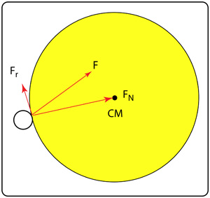
Figure 1 — Component forces of string force. Friction acts parallel to the string surface and the normal reaction force acts perpendicular to it.
When a ball bounces off a solid surface or a full racquet stringbed, we tend to analyze the bounce and spin in terms of the friction and the normal forces rather than the total force, F. Of course, such an approach can be done for a single string also, as in Figure 1. But the beauty of the 4-string experiment is that it allows us to see each string force in action. We can literally see angle, direction, and magnitude of the each force (F in Figure 1). This is a much more intuitive way to look at the impact instead of having to break the force into components. In this way, we can use this knowledge to extrapolate what is happening in a stiff, closed pattern, high tension stringbed, even if we can't see it. We will use this technique in the discussion that follows.
II. THE EXPERIMENT
1. Plexiglass Rig Setup
In order to see the amount of string deflection, the angle of deflection, the relative motion of the ball on the string, and the string snap-back, a plexiglass "racquet" was created. Both a "no-crosses" (Figure 2) and a "with-crosses" (Figure 3) stringbed was tested.
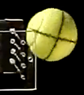
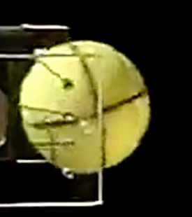
Figure 2 — Plexiglass Window. Typical impact as seen through the plexiglass window. The incident trajectory is created by wrapping the ball in a ribbon to produce spin as it drops and unwinds onto the stringbed. The ball drops vertically from about a meter onto a stringbed that has been tilted to the desired angle. The film here has been rotated 90 degrees to see the impact horizontally as one would on a court. The average drop speed was about 8.0 mph (3.6 m/s), incident angle about 37 degrees (the angle between the incident path and the direction perpendicular to the string plane), and the spin was about 605 rpm (63.3 rad/s).
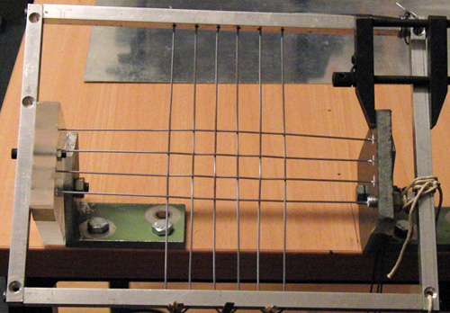
Figure 3 — Rig with crosses added. The sidebars for the crosses support were secured above the main string holes so that string movement as seen from the side through the plexiglass was unimpeded.
A camera was setup to the side to view the impact through the clear glass string holder. Holes were drilled in the plexiglass and the string was inserted and tensioned with weights hanging from the opposite side string support. The string span was 200 mm long and the space between strings was 14 mm (about the maximum on the market). Each main string was tensioned with a 3.35 kg weight and the cross strings were hand tensioned. The stringbed had only four main strings, each at low tension so that the stretch of each string could easily be observed on video film.
First, the no-crosses condition in both the unfiled and filed (with a rat-tailed file) condition were tested. Then crosses were added and tested in both the unfiled and filed condition. The stringbed with crosses was composed of 4 mains and 6 crosses.
The ball was dropped vertically from a fixed position about a meter above the stringbed. The stringbed could be oriented at various angles to the oncoming ball. The primary angle was about 37 degrees and incident speed was about 3.6 m/s. Incident spin was created by wrapping a ribbon or string around the ball and dropping from a fixed location. As the ball dropped and unwound from the ribbon, spin was created. The amount of spin could be varied by changing the length of the ribbon wrapped around the ball.
A camera filmed the impact from above at 300 frames per second, and another filmed from the side at 600 fps. Both cameras were used to determine best impacts and only those that hit all four main strings were counted as good. The main strings were referenced by numbers 1 to 4 counting from the top.
2. Test Strings
One string was used for the testing — a smooth, round polyester, which was filed with a rat-tailed file to increase roughness. The roughness created was not simply in texture but also in having frayed appendages that act as hooks or snares to the fibers of the ball felt. A comparison of the two test surface conditions is presented in Figure 4.
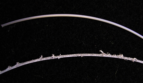
Figure 4 — String Surface Conditions. The surface conditions of the string are normal or unfiled (top) and filed (bottom).
The static coefficient of friction of the string on the ball was determined using a device similar to the one described in How String-To-Ball Friction Affects Spin. The COF for the smooth, unfiled string was 0.406 and 0.77 for the filed string. It is evident that roughing the surface increased the string-to-ball coefficient of friction. Does this in turn increase spin?
3. Measurement
Digitization. Figure 5 shows the essentials of measurement. The center of mass (CM), pre-impact center of the string, and the deflection of the string from center were digitized, as was a point on the periphery of the black lines drawn on the ball. This digitization facilitated calculations of velocities, forces, torques, directions, angles, durations, deflections, and spin.
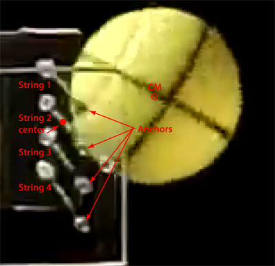
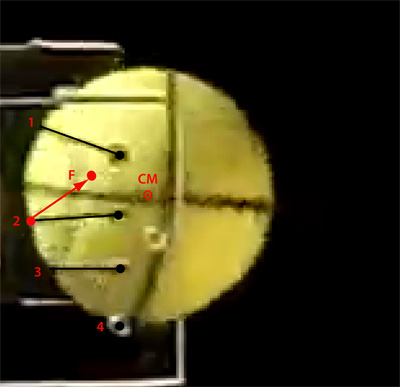
Figure 5 — Measuring string deflection. The first image shows the center of string 2 just before impact. The force exerted by the string on the ball will always be in the direction back to its starting center location. The second image is of the same string at peak impact (note: the bottom string 4 can't be seen because it is hidden under the ball). The force line is directed back to the pre-impact center (shown by the red dot). A similar digitization was done for each string (main strings only in stringbed with crosses).
The force exerted by each string changes magnitude and direction during the impact. The center of each string deflects from its pre-impact location (the red dot at the end of the force line). It stretches in both the horizontal (y axis perpendicular to string plane) and vertical plane (x axis parallel to string plane). The line of force for each string is directed toward the pre-impact location. The pre-impact center lies half-way between the anchor points of each string. The force on the ball is directed through this center point, not along the string through the anchor point.
Geometry of impact. The geometry of string deflection is shown in Figure 6.
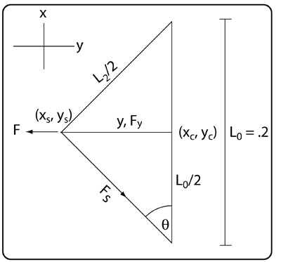
Figure 6 — Geometry of string deflection — view from top. F is the perpendicular force stretching the string (and the equal and opposite force on the ball), Fs is the force along the string pulling back from each side, Fy is the y axis component of Fs pulling from each half of the stretched string, L0 is the string length before impact, L2 is the length of the stretched string, y the deflection distance, (xc, yc) the coordinates of the pre-impact center of the string, and (xs, ys) the coordinates of the deflected string.
From that geometry the force of each string on the ball was calculated using measurements of the string deflection, angle of deflection, elongation, and the stiffness of the string. The force on each string is given by
[2] F = 2Fssinθ = 4kxy / L2
where F is the force on the string (and the equal and opposite force on the ball), Fs is the force along the string, k the longitudinal string stiffness, x is the longitudinal elongation = L2 – L0, y is the deflection, L2 is the length of the stretched string, and θ is the angle of deflection from the string anchor point to the deflected center of the string length. Only the string stiffness was not directly measurable and had to be assumed. Its value was "backed into" by comparing predicted results to actual results and adjusting k to make them agree. From that the force on the ball could be calculated.
Net resultant force. The description of the ball's translational and rotational motion was completely derived from the magnitude and direction of string forces as shown in Figure 5. The individual string forces were then combined by vector addition to get a single, net resultant force. The resultant force at any given time is a single equivalent force to the combined forces of the 4 individual strings. Such a force is shown in Figure 7.
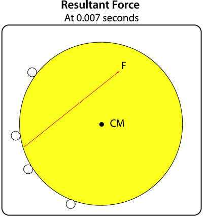
Figure 7 — Resultant force at 0.007 seconds. The force line shows the magnitude, direction and line of action of the resultant force. The line of action of resultants are calculated by summing forces and torques and then working out the axes intercepts. A single resultant force generates the same ball velocity and spin as the four separate strings do. The force vector shown here is the same as #4 in Figure 8.
Figure 8 shows an example of the frame-by-frame resultant force. The length of the force lines indicate the magnitude of the force and the arrow is the direction of action. Resultants were calculated by summing forces and angles and then calculating the x (vertical) and y (horizontal) axis intercepts. All force lines pointing above the CM generate topspin (lines 1-7) and all below act in the opposite direction, reducing topspin (lines 8-11).
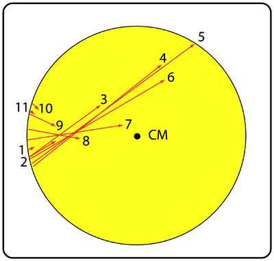
Figure 8 — Force resultant over time. The length of each numbered line represents the magnitude and the arrow indicates the direction of the force resultant in 0.001667 second intervals. The force increases up to peak deflection and then decreases as the ball rebounds.
Torque and moment arm. Force magnitude and direction is only part of the story. The effect of the force on spin depends on the perpendicular distance from the force line to the CM, known as the moment arm. The force times the moment arm equals torque (Figure 9). If the force line is too short to draw a perpendicular to the CM (like most of the lines in Figure 8), simply extend a virtual projection of it far enough to do so.
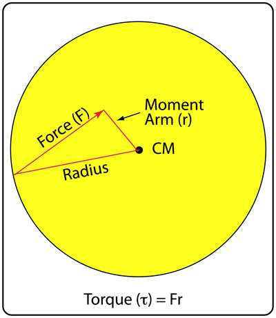
Figure 9 — Torque. Torque is equal to the force magnitude times the perpendicular distance from the line of force to the ball's center of mass.
It is torque that is responsible for rotation, not simply force. Torque is given by
[3] τ = Fr
where τ is torque, F is force and r is the length of the moment arm.
It is possible to have a large force with very small moment arm or a large moment arm but small force. It is the product of the two that determines the magnitude of torque. Figure 10 shows the resultant torque of each of the force lines in Figure 8. Force lines 7, 8, and 9, though relatively large, have small moment arms and thus low torque.
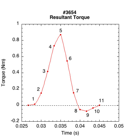
Figure 10— Torque resultant over time. Each number corresponds to a force line in Figure 6.
Direction of force, friction, and torque. The interesting observation is that the force lines in frames 8-11 point below the CM and have negative torque. This means that the strings are undoing some of the topspin that they created earlier. The torque, and by extrapolation, the friction, has been reversed by the end of the impact. As mentioned in the Introduction, friction reversal occurs when Vc reverses direction. We see here that also coincides with a "direction reversal" of force, F, on the ball. Reversal here means changing the pointing of the force arrow from above the CM to below the CM. In this sense, "friction reversal," "force reversal," and "torque reversal" are interchangeable terms.
III. RESULTS
1. No-Crosses Results
Individual Impact Results. Figure 11 shows a comparison of the torque by string for both the unfiled and filed condition during impact.
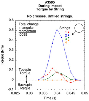
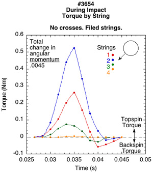
Figure 11 — Torque by string for unfiled and filed strings. The sum of the areas under each string's curve (total change in angular momentum) is greater for the filed strings than that for the unfiled. However, the filed strings experience more friction reversal at the end of the impact, undoing some of the work that they did earlier in the impact.
Each string contributes a different amount of torque. Here, string 2 and 1 produce the most torque and string 4 barely contributed. On the filed string, string 1 and 3 produced the most negative torque. Though looking at the individual strings is instructive, ultimately, what we are interested in is the net torque of all four main strings in sum and the spin generated by this torque (Figure 12).
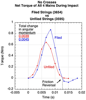
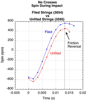
Figure 12 — Net Torque of all 4 mains strings (left or top) and spin (right or bottom). In this example, both impacts have been placed on the same time axis. The filed string not only generates more topspin torque, but also has a greater torque reversal toward the end of the impact. Both string conditions display some torque reversal at 0.013 seconds and this is reflected as a decreasing in spin at that moment.
As the torque goes to 0 or negative, the spin reaches a peak and then decreases. The average contact velocity (Vc) of all 4 strings should change direction at this same instant, as indeed it does (Figure 13).
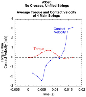
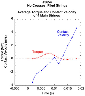
Figure 13— Net torque for all four strings vs average contact velocity of strings: Unfiled (left or top) and filed (right or bottom). As the contact velocity reverses direction toward the end of the impact, so too does the torque direction and spin starts to decrease.
It should follow that if there is more torque and spin, there should also be greater lateral deflection of each string. Likewise, if torque is negative, then there should be more negative deflection of that string, more negative torque, and more decrease in spin. This is the case (Figure 14).
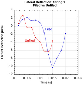
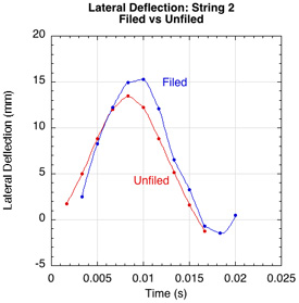
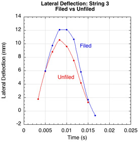
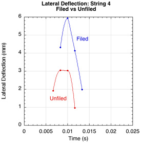
Figure 14— Filed vs unfiled lateral deflection by string. For all 4 strings, the filed string had more lateral deflection than the unfiled. More lateral deflection means more torque.
The filed strings exhibit more lateral deflection, indicating that there was less string slippage than with the unfiled, smooth strings. Interestingly, the lateral displacement changes direction at the end of the impact for strings 1 and 2. This indicates that at the end of the impact snap-back undoes some of the topspin that it has created — "reverse snapback". That is why the peak spin is usually about 0.03 seconds before rebound.
This peculiar change in the direction of lateral displacement for strings 1 and 2 can be seen in Figure 15. Each string starts at the red diamond and then travels a clockwise elliptical trajectory. Strings 1 (top) and 2 first travel down and then upward, above the starting location. At this point they are exerting a backspin torque. The spin and direction of the ball initially moves the strings downward, but once the spin direction changes, the ball moves the strings upward (and vice versa).
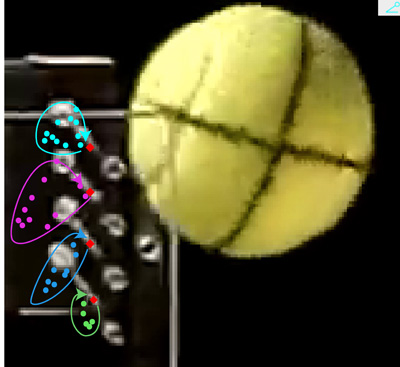
Figure 15 — Deflection trajectories of each string. The incident ball comes in with backspin and pushes the string down and back. As the spin becomes topspin, the ball "spins" the strings upward. The trajectory path of each string is clockwise and nearly elliptical.
Average Impact Results. The above discussion focuses on the results of just one impact each for an unfiled and filed string. This was so we could focus on the mechanisms involved in actual impacts. These mechanisms were apparent in every impact for both filed and unfiled strings. The sample impacts above show the filed string producing a bit more spin. When we take the average of the 4 good impacts we had for each the filed and unfiled condition, that advantage averaged out. The average spin of all 4 filed and 4 unfiled impacts was about the same (unfiled = 396 rpm and filed = 370 rpm, about 7% less for the filed strings). The reason is that the filed strings, having higher friction, reverse the spin more quickly and therefore go into friction reversal sooner than the unfiled strings. In the end, sometimes the filed strings produce a bit more spin and sometimes not. But on the average, they both produce about the same spin. The filed string may produce more peak spin and then lose it and have less ending spin, whereas the unfiled may produce less peak spin but not lose much if any and end up with more. But the main point here is that if both strings are close to Vc = 0, whether above or below, That means that they are both oscillating about that equilibrium point.
The rebound angle was greater for the filed strings compared to the unfiled: 19.9 vs. 17.3 degrees. This is to be expected since there was more force directed upward with the filed vs. unfiled strings.
2. With-Crosses Results
The addition of crosses changes the dynamic of string movement. Now, the stringbed is much stiffer and there is inter-string friction acting against lateral string movement in both directions. Also, the crosses block the ball's access to the main strings, making it more difficult to grab and move them.
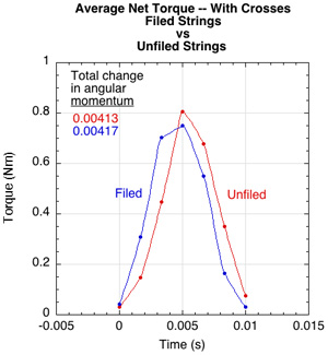
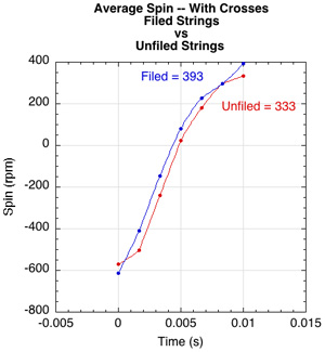
Figure 16 — Combined torque and spin for all impacts. Average combined torque for all impacts (left or top), and average combined spin for all impacts (right or bottom) for filed and unfiled strings with crosses.
The average impact time is about 2/3 that of the no crosses stringbed (0.01 compared to 0.015-0.018 seconds) but the forces are higher. Also, there is no friction reversal in these tests. There is not enough friction to reverse the contact point velocity, so torque works throughout the impact to increase topspin (Figure 17).
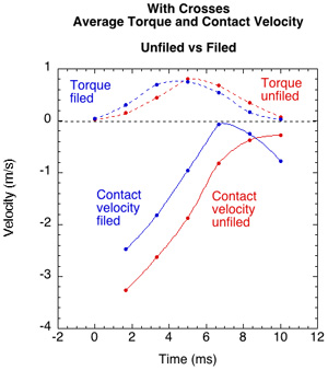
Figure 17 — Average Torque and contact velocity for unfiled and filed string with crosses. Contact velocity and torque never reverse.
As with the no-crosses stringbed, the average net string deflection and parallel displacement were greater with filed strings.
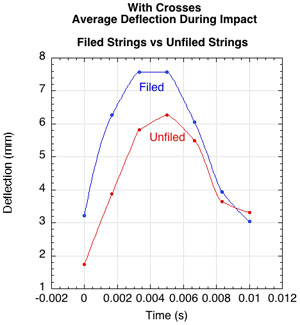
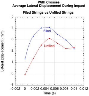
Figure 18 — Average net string deflection (left or top), and average lateral string displacement (right or bottom) for filed and unfiled strings with crosses.
The rebound angle for the filed strings was greater, 3.4 compared to -6.6 degrees, a 10 degree difference. The rebound actually reversed direction with the filed strings but continued in the direction of the incident ball on the unfiled strings.
3. Comparing Crosses and No Crosses
Figure 19 and Tables 1-3 that follow compare filed and unfiled conditions for stringbeds with and without crosses.
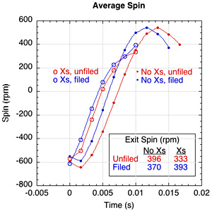
Figure 19 — Average spin for all string/pattern combinations.
The stringbed without crosses did indeed achieve a greater peak spin value, but then reversed it. The stringbed with crosses simply kept producing spin, slow and steady. It is interesting that the filed-with-crosses strings produced more spin than the filed-no-crosses strings.
IV. DISCUSSION
The evidence suggests that in both stringbeds with and without crosses, filed strings have higher torque earlier, earlier friction reversal (if there is one), more x and y axes deflection, and higher launch angle. Spin, however, was situation specific — spin was greater for filed strings with crosses but less without crosses, which, initially, was surprising. In all cases except the spin exception, the difference between crosses and no-crosses was larger on every parameter than the difference between filed and unfiled.
The stringbed with crosses was stiffer (more strings), produced higher forces, had shorter dwell time, and limited ball access to the higher COF main strings. Under those conditions, the dwell time was not sufficient for friction to reverse, so spin kept increasing. But during this time, as long as Vc ≠ 0, the additional friction of the filed condition increased torque and spin compared to the unfiled condition.
In the no-crosses stringbed, there was plenty of time for both filed and unfiled stringbeds to achieve Vc = 0 and maximum spin, and thereupon a friction reversal. Since the equilibrium value of spin is determined by contact velocity equal to zero, both filed and unfiled conditions oscillate around that value and thus achieve similar results, given enough time — reversal followed by reversal followed by reversal ....
String "Snap-back" Revisited and Redefined
"Snap-back" has been defined as the return to position of a string that has been laterally displaced parallel to the stringbed. This tangential return was seen as adding extra spin. In videos of impacts taken from behind a stringbed, the visual evidence of this snap-back was very compelling (Movie Screen 2).
Movie Screen 2 — Lateral string movement from behind (1200 fps). As seen from behind, the impression is that spin augmentation occurs because the strings slide up the back of the ball during the snap-back phase.
(Note: Use "double-arrow" movie controls for frame-by-frame play.)
From the back view, snap-back is visualized as totally vertical and delayed. But, when seen from the side, the strings are moving diagonally away from the camera's view and returning to the pre-impact location. Also, as we will see below, the lateral stretch of the string adds torque throughout impact, not just at the end (Movie Screen 3).
Movie Screen 3 — Lateral string movement from the side (600 fps). The side view shows the diagonal stretch and return of the string. There is no "brush up the back" of the ball per se at the end of the impact.
(Note: Use "double-arrow" movie controls for frame-by-frame play.)
An amended description of "snap-back" is required as it relates to spin production due to lateral string movement. Figure 20 shows the displacement of string #2 throughout impact (note: these force lines are for an individual string, not the resultant of all 4 strings as in Figure 6). There is both vertical and horizontal displacement. The reaction force of the string on the ball is back toward the pre-impact center of the string (red dot on force line). As the string moves downward, the angle between the pre-impact center, the string, and the ball CM increases, and with it the length of the moment arm increases (perpendicular distance from force line to the CM — not drawn).
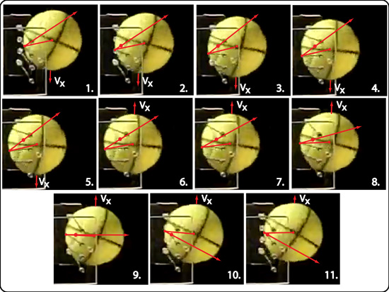
Figure 20 — No Crosses: Perpendicular and parallel displacement of string #2. The displacement of the string (red dot on periphery of ball) is shown from the pre-impact center of the string (red dot along force line). When the force arrow is directed above the ball CM, the torque increases topspin. When below, the torque diminishes topspin.
The moment arm is essentially a lever that the force uses to rotate the ball. The direction of the force line determines the length of the lever arm. So lateral deflection is important because it increases leverage — or to coin a term, it increases "spin leverage." Spin leverage can be either positive or negative. The spin lever lengthens as soon as there is lateral deflection. For that reason, lateral deflection influences spin throughout the impact, not just at the snap-back phase. In fact, most of the change in spin occurs during the stretch of the string, not during the snap-back phase. This is because the ball spends less time on the strings during snap-back than during stretch because the racquet is propelled backward away from the ball.
Snap-back is a limited view of a three-dimensional continuous process as seen in two dimensions from behind the stringbed. The key is to get the string moving laterally. Then extra torque is supplied throughout the impact, not just at the end. Lateral string movement increases the spin leverage.
Once the stringbed becomes denser and stiffer with more strings and higher tensions, it is no longer possible to isolate increases in spin leverage generated by individual strings. When you can't measure the individual forces, you have to measure the velocity and rotation parameters before and after impact in calculate what the force and torques were during impact to account for the change. However, the processes observed in this experiment will still be causative factors even if they can't be individually measured.
V. CONCLUSION
A tennis player wants to utilize the extra COF to its limit, without crossing the boundary into negative torque. One way to delay or prevent the onset of friction reversal is to swing faster. That increases the relative velocity of the ball to the string so that the incoming spin has to be changed a lot more in order to bring Vc to 0. Consequently, those with slow swings are less likely to reap the benefit of high COF strings compared to faster swingers.
Another strategy is to swing at a steeper angle or tilt the racquet forward. Both these techniques, like swinging faster, will increase spin whether or not you have a high COF string surface. Increasing the ball's incident angle delays the occurrence of contact velocity reversal and increases spin (Figure 21).
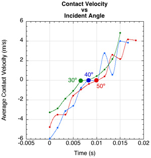
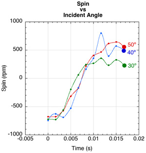
Figure 21 — Increasing incident angle delays Vc = 0 and increases spin. Increasing the incident angle increases the incident contact velocity and lowers the normal force and thus the friction force. That combination results in a greater relative ball-to-string velocity to reverse and more time to do it. That gives a higher COF string more time to increase spin compared to a low COF string.
More friction creates more spin, but there is always a limit. That limit occurs when
Vxb - Vxs = Rω
or, equivalently
Vc = Vxb + Rω - Vxs = 0
For most practical racquet setups with normal string patterns (i.e., not "spaghetti" patterns), friction reversal will not occur. Reversal occurs when ball Vx and rebound angle also get reversed. This does not happen on normal patterns at normal speeds. Look again at Figure 20. Starting with frame 6, Vx changes direction from vertically downward to upward (red arrows labeled "Vx"). As the ball moves and spins up, and as the string begins to snap back, the string moves upward also. As it does so, it first becomes horizontally aligned with its pre-impact center and then moves above that center. The force direction then reverses, as indicated by the force arrow. This means that the spin lever arm has moved below the ball's CM and we now have negative spin leverage. Visualizing spin production by means of force arrows and leverage direction is much easier than grappling with friction force reversal with all its component forces and relative velocities.
Compare Figure 22 (with crosses) with Figure 20 (no crosses) to see the difference between a friction reversal and non-reversal. On Figure 22, the force arrows alway point up and the ball Vx is always directed downward.
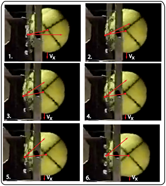
Figure 22 — Crosses: Perpendicular and parallel displacement of string #2. The displacement of the string (red dot on periphery of ball) is shown from the pre-impact center of the string (red dot along force line). The string displacement never goes above horizontal alignment with the pre-impact center and the spin lever, friction, contact velocity, and Vx never reverse.
In the end, you are likely to get more spin with a string with a higher string-to-ball coefficient of friction. Perhaps not always and probably not a great deal more. More and more friction does not mean more and more spin. More string-to-ball friction definitely increases torque, but it does so for less time. A lower COF string will have lower average friction force, but it will maintain it for a longer period of time. Both strings work to increase spin until the contact velocity equals 0. At Vc = 0, both the high and low COF strings will have achieved the same spin (assuming they are the same string but one has been roughed up). But since strings of differing COFs change spin at different rates, the exit spins are likely to be different. The string with the most spin will be the one whose Vc was closest to 0 when the ball leaves the stringbed.
Related Tennis Warehouse University (TWU) Web Pages
1 "Impact of a Tennis Ball with a Single String"
2 "Which Strings Generate the Most Spin?"
3 "String Movement and Spin"
4 "String Snap-Back and Spin"
5 "Spin and String Pattern"
6 "Sliding Friction and Spin"
7 "Static Friction and Spin"
8 "String Stiffness and Spin"
9 "Spin and String Lubrication"
10 "Spin and String-to-Ball Friction"