1. Flex ratings of hockey sticks
The flex ratings of hockey sticks provide a useful guide to the flexibility of a stick but they can also be confusing or even misleading. The first problem is that an increase in flex corresponds to a decrease in flexibility. That is, as the flex rating increases, the flexibility decreases or the stiffness increases. Another problem is that the flex usually varies along the stick. Furthermore, it is hard to find a clear definition of what is actually meant by the term "flex". Everyone agrees that the flex is the force in lbs needed to bend a stick by one inch. If it takes 85 lbs, then the flex is 85. Practically everyone agrees that cutting a stick shorter by 2 inches will increase the flex by about 10 units. The first statement is partly correct but the second statement is wrong.
The force needed to bend a stick by one inch depends on the bending length. To measure the flex, the shaft is usually supported at two points a distance L apart, then the force is applied half way between the two supports. The standard test distance is L = 1.0 m. However, if L is shortened to say 0.5 m then the force to bend the stick by one inch will increase by a factor of 8. If it takes 85 lb to bend a one meter section of the stick by one inch, it will take 680 lbs to bend a 0.5 m section of the same stick by one inch.
Usually, the stick is bent over a distance of 1.0 m to get an industry standard answer for the flex of a stick. However, the result depends on which 1.0 m section of the stick is bent. It could be bent over a 1.0 m length starting at the butt end, or it could be bent over a 1.0 m length starting at the blade end. Most manufacturers measure the flex of their sticks by bending them over the middle section, with 20 cm or so at each end hanging freely beyond the two supports.
The ends of the stick extending beyond the two supports do not bend at all. If 2 inches are cut off the butt end then the flex will not be affected. Exactly the same force will be needed to bend the 1.0 m middle section by one inch. However, if you cut a stick 2 inches shorter, then you will probably move your hands closer together when swinging and bending the stick. That will make it harder to bend the stick, regardless of whether you cut the stick short or not, so it will feel like a stiffer stick, even though the flex of the stick itself is not altered when it is cut shorter.
2. Flex variation along the shaft
Some sticks are more flexible at the blade end, some are more flexible at the handle end, and some are more flexible in the middle. The flex rating of a stick is just the average flex over a 1.0 m long section in the middle. In order to measure the variation in flexibility along the shaft, the authors took a sample of 13 high performance sticks and bent them over five different 0.6 m long sections from one end to the other. Each section started 0.2 m from the next and overlapped the next section, as indicated in Fig. 1. A vertical force, F, was applied in the middle of each section, as indicated by the arrow, and the vertical deflection, y was measured in order to calculate the stiffness k = F/y of each section. The deflection, y, was only about 5 mm in this test since a deflection of one inch over each 0.6 m length could easily have broken the stick.
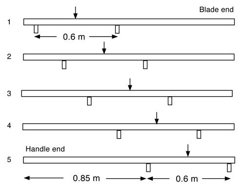
Figure 1 — The five sections of the stick used to measure the flex. The 60 cm flex zones started at 5 cm from the end of the stick and progressed down the stick in 20 cm intervals.
The flex of each stick was also measured by bending it over a 1.0 m length in the middle of the shaft. The results were very close to those quoted by the manufacturers. In theory, the flex over a 0.6 m long section of the shaft is 4.63 times larger than the flex over a 1.0 m long section, since the shaft stiffness is inversely proportional to the cube of the bending length. In order to compare the flex over each 0.6 m long section of the shaft with the flex over the 1.0 m long section, we divided the measured stiffness of the shorter sections by 4.63 to provide a meaningful comparison. That way, the flex of each short section could be compared directly with the average flex of the 1.0 m long middle section.
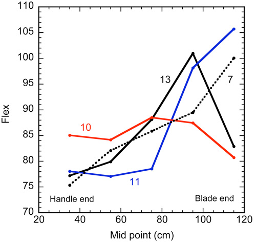
Figure 2 — Variation of flex along sticks 7, 10, 11 and 13.
A few results are shown in Fig. 2 and results for all 13 sticks are shown in the Table below. In the Table, Flex is the value measured over the middle 100 cm, F35 is the value measured 35 cm from the handle end (from 5 cm to 65 cm) and F115 is the value measured 115 cm from the handle end. Also shown is the release time, T, in milliseconds, which is discussed later.
All the sticks were tapered near the blade end of the shaft, which would normally make them more flexible at the blade end. The tapered section also widened which would act to stiffen the blade end of the shaft. Most of the sticks were more flexible at the thicker handle end and stiffer at the thinner blade end. Some were more flexible in the middle. Stiffness along the shaft is also varied by the manufacturer by changing the wall thickness or shape of the tube or by using different grades of graphite in different sections of the shaft.
| Table 1 Flex of Each Stick at 5 Different Locations | |||||||||
| Stick | Brand | Model | Flex (Middle 100 cm) (lb/in) |
Flex at 35 cm (lb/in) |
Flex at 55 cm (lb/in) |
Flex at 75 cm (lb/in) |
Flex at 95 cm (lb/in) |
Flex at 115 cm (lb/in) |
Release Time (ms) |
|---|---|---|---|---|---|---|---|---|---|
| 1 | Bauer | Supreme 18 | 83 | 74 | 75 | 79 | 99 | 96 | 22.5 |
| 2 | Bauer | Nexus 1N | 83 | 75 | 82 | 83 | 87 | 81 | 23.0 |
| 3 | Bauer | Vapor 1X | 87 | 84 | 87 | 88 | 91 | 78 | 20.7 |
| 4 | Sher-wood | Rekker EK60 | 88 | 83 | 87 | 88 | 89 | 87 | 22.0 |
| 5 | Sher-wood | BPM 150 | 88 | 85 | 85 | 87 | 90 | 91 | 22.8 |
| 6 | Sher-wood | BPM 90 | 90 | 78 | 85 | 89 | 97 | 94 | 23.0 |
| 7 | Warrier | Covert QRL | 87 | 75 | 82 | 86 | 89 | 100 | 21.7 |
| 8 | True | XCore 9 | 83 | 74 | 76 | 83 | 93 | 88 | 23.0 |
| 9 | True | A6.0 SBP | 79 | 76 | 75 | 78 | 85 | 84 | 23.3 |
| 10 | CCM | RibCor Trigger | 89 | 85 | 84 | 88 | 87 | 80 | 22.2 |
| 11 | CCM | Super Tacks | 83 | 78 | 77 | 78 | 98 | 106 | 22.5 |
| 12 | CCM | RBZ Revolution | 90 | 90 | 88 | 91 | 90 | 96 | 22.8 |
| 13 | STX | Surgeon RX2 | 90 | 77 | 80 | 88 | 101 | 83 | 22.0 |
Table 1 — Flex of each stick at 5 locations as measured in the middle of a 60 cm span. The 60 cm flex zones started at 5 cm from the end of the stick and progressed down the stick in 20 cm intervals.
3. The kick point
The variation in flex along a stick is commonly described in terms of the kick point of the stick. Hockey sticks are usually described as having either a low kick point or a mid-kick point or a variable kick point (depending on the location of the hands). A mid kick point is often claimed to help generate high puck speed, while a low kick point allows for a quick release of the stored elastic energy in the stick. Players who use their slap shot more often may prefer a mid kick point stick and players who use wrist shots more often may prefer a low kick point stick.
The kick point is usually described as the point on the shaft that flexes or bends the most. However, photographs of bent sticks show that the stick bends most at a point close to where the player pushes on the stick with the lower hand. The photographs are not telling lies.
Suppose that a stick has a constant flex or stiffness along its whole length, is supported at two points say 1.0 m apart and is pushed down in the middle. The shape of the stick will then be as shown in Fig. 3. The stick bends the most in the middle even though the ends of the stick are just as flexible as the middle section. The ends of the stick, including the points directly above the supports, don't bend at all. Consequently, the flexibility of a stick does not necessarily determine the point that bends the most. For a uniform stick, the point that bends the most is the point where the force is applied. Even if the flexibility of a stick varies along its length, the point that bends the most is very close to where the force is applied, rather than at the point where the stick is most flexible.
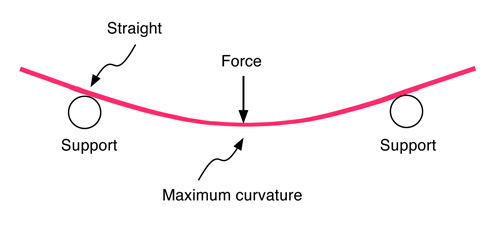
Figure 3 — Bending shape of a stick supported near each end.
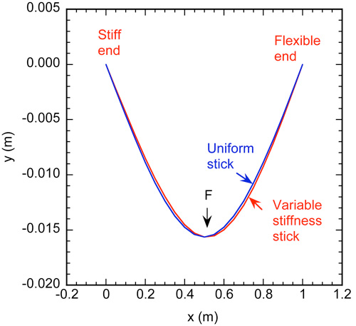
Figure 4 — Bending shape of a uniform stick compared with one that is twice as flexible at one end than the other. In order to show the difference more clearly, the y scale is magnified compared with the x scale.
Suppose that a stick is twice as flexible at one end than the other, the flex increases smoothly from one end to the other, it rests on two supports 1.0 m apart and a force is applied in the middle. Calculations show that the shape of the stick is almost the same as that in Fig. 3 and the stick remains straight at both ends. The more flexible region bends slightly more than the stiffer region, as shown in Fig. 4, but the difference would be very diffcult to detect by eye.
Even if the bending force is applied near one end, the shape of the stick is basically the same as that in Fig. 3. A calculation for a uniform stick is shown in Fig. 5, where the stick was supported at two points 1.0 m apart and a vertical force was applied at a point 0.2 m from the left end. In that case, maximum deflection occurs at a point 0.44 m from the left end rather than in the middle.
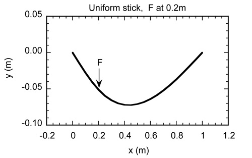
Figure 5 — Bending shape of a uniform stick, with supports separated by 1.0 m, when the bending force is located 0.2 m from the left hand support.
4. Stiffness of a hockey stick
When a player strikes a hockey puck, a force is applied at the bottom end of the stick and the stick is supported by the hands, one near the handle end and one near the middle. Consequently, the situation shown in Fig. 3 is not directly relevant. A more relevant flex or stiffness measurement is the one shown in Fig. 6, where the handle end is inserted between two rods located a distance L1 apart and a load is applied at the blade end. For a stick of uniform stiffness, the deflection, D, at the blade end is given by
D = (FL / 6EI) (2L2 - 4L1L2 - 2L12)
where EI represents the bending stiffness of the material used to construct the stick, and L = L1 + L2 is the length of the test region. E is Young's modulus for the material and I depends on the shape of the material (width, wall thickness etc). For example, if L1 = L2 = L/2 then
D = FL3 / 12EI
In Fig. 3, the deflection at the middle of a uniform stick is given by
D = FL3 / 48EI
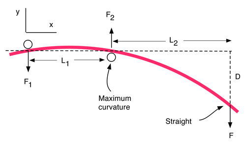
Figure 6 — Bending shape of a uniform stick, with supports separated by a distance L1, when the bending force is located near the blade end of the stick.
The behavior of a hockey stiff depends on its stiffness, k, which is defined as k = F/D. It is measured in lb/inch or Newton/m and it depends on the flex of the stick and the actual bending length, L. For example, in Fig. 3, k = 48EI / L3, and in Fig. 6, k = 12EI / L3 when L1 = L2 = L/2. For the same bending force, the deflection in Fig. 6 is therefore 4 times larger than the deflection in Fig. 3 so the stick in Fig. 3 is 4 times stiffer than the stick in Fig. 6, even though it is exactly the same stick. The difference is not the stick itself, but the point where the force is applied. If the same forces are applied in the middle and ends of the stick, in both Figs. 3 and 6, then the shape of the bent stick will be the same in each case. In Fig. 3, the deflection is measured in the middle of the stick and it is half the deflection value at the end of the stick indicated in Fig. 6. In addition, the force in the middle of the stick is twice the value at each end (at least when L1 = L2) so the stiffness in Fig. 3 is 4 times larger than the stiffness in Fig. 6.
The stiffness of most of the sticks in the above table, labelled as the "Flex", is about 85 lb/in or 14,886 N/m. Since k = 48EI/L3 in this test and L = 1 m, the value of EI for all the sticks is about k/48 = 310 N/m2. That value can be used in any of the above formulas to estimate the deflection or the stiffness for any test method.
The stiffness of each of the 13 sticks was measured using the arrangement shown in Fig. 6 with L1 = 50 cm and L2 = 86 cm. The deflection at the blade end of the stick was measured by hanging a 5.35 kg mass on the blade end. The deflection varied from 59 mm for the stiffest sticks (sticks 6 and 12) to 68 mm for the most flexible stick (stick 9). Consequently the stiffness varied from 770 N/m to 890 N/m in this test. If L1 was longer and L2 was shorter, then the stiffness of each stick would have been larger, meaning that it would be more difficult to bend a stick if the bottom hand is moved further down the shaft.
5. Release time
When a player strikes a puck, the stick bends by an amount that depends partly on the force exerted on the stick by the player and partly on the the force exerted on the blade by the puck. After reaching its maximum deflection, the stick then starts to straighten out, gaining speed at the blade end as it does so, and giving the puck an extra kick forward. There are two separate aspects of this process that are of interest to players. One is the time that it takes to release the stored elastic energy in the stick, usually called the release time. The other is the extra speed given to the blade and the puck as a result of the energy release. The extra speed depends on the amount of elastic energy stored in the stick, so it depends on how far the stick is bent.
The release time does not depend on the amount of energy stored or on the actual bend in the stick. It depends on the mass and the stiffness of the stick. If the stick is stiff then it will spring back to its straight position quickly. If the stick is heavy, especially at the blade end, then it will spring back slowly, regardless of the actual bend in the stick. One way to measure the release time is to measure how fast the stick vibrates back and forth when it is clamped. Those vibrations are normally damped quickly when a player is holding the stick, but can be felt as a sting in the hands immediately after striking the ice or the puck. However, if the stick is clamped firmly at some point along the shaft and if the blade is pulled down and then quickly released, then the stick will first straighten out and then bend in the opposite direction since the stick reaches maximum speed as it returns to the straight position.
To conduct this test, each of the sticks was clamped in a horizontal position at the handle end and also at a point 50 cm from the handle end so that middle of the blade was located 86 cm from the 50 cm clamp point. The blade was then pulled down by hand a distance of about 9 cm and quickly released, causing the blade to vibrate up and down about 11 times per second. Each complete vibration cycle therefore took about 0.09 seconds. The time from the lowest to the highest point was half that, or 0.045 seconds, and the time from the lowest point to the straight (horizontal) position was half of that again, or 0.0225 seconds. It is the latter time that is of interest, although the actual release time is longer since the puck adds to the total weight of the blade and the shaft and slows down the release. The release time, based on the measured vibration of each stick, is shown in the above Table 1. There was a surprisingly small variation between sticks, most with a release time between 22 and 23 milliseconds. It is doubtful that an extra one millisecond in release time would be noticed by a player.
6. Flex energy vs kinetic energy
It is interesting to compare the amount of elastic energy stored in a hockey stick with the energy given to the puck. The kinetic energy of any object of mass m and speed v is 0.5mv2. For a 170 gram puck traveling at 30 m/s (67 mph), the kinetic energy is 76.5 Joules.
When a player bends a hockey stick, the stiffness of the stick is typically about 1000 N/m depending on where the player holds the stick. When the stick strikes a puck, the stick bends even further at first and then straightens out as the elastic energy stored in the stick is transferred to the puck.
The elastic energy stored in the stick is given by 0.5kx2 where x is the deflection. For example, if k = 1000 N/m and x = 0.2 m, then the stored energy is 20 Joules. In theory, that energy could be used to launch a puck at a speed of 15.3 m/s since the kinetic energy of the puck would then be 20 Joules. However, part of the stored elastic energy is used to accelerate the stick itself. If the bent section of the stick weighs 0.17 kg, and the puck weighs 0.17 kg, then roughly half the elastic energy will be given to the puck and the other half is used to accelerate the stick.
Suppose that the puck accelerates to 10.8 m/s and ends up with 10 Joules of kinetic energy. It was accelerated over a distance of 0.2 m and traveled that distance at an average speed of 5.4 m/s so it took 0.037 s to reach maximum speed. That is the release time of the stick. The release time can be shortened by using a stiffer stick or by moving the bottom hand closer to the blade so the stick bends over a shorter length.
Suppose that k = 2000 N/m instead of 1000 N/m and the same 200 N force is used to bend the stick. Then x = 0.1 m and the stored energy is 0.5 x 2000 x 0.12 = 10 Joules. To get the same 20 Joules as before, the force would need to be increased to 280 N, giving x = 0.14 m. If the puck is ejected at 10.8 m/s as before, ending up with 10 Joules of energy, then it accelerates over a distance of 0.14 m at an average speed of 5.4 m/s. In that case, the release time is 0.14/5.4 = 0.026 seconds. The player can therefore release the puck sooner with a stiffer stick but has to push harder on the stick to bend it, and ends up with the same puck speed.
The puck speed that can be imparted just by bending the stick is not very large. More commonly, players push or flick the stick forward while bending it, in order to increase the force on the puck. Even higher puck speeds result when the stick is first accelerated and then collides with the puck.